


 53Likes
17.5 Motor Power Output from Dyno
 03-14-2024, 08:21 PM
#91
Okay, that's a little better. However, we need timing degrees corresponding to the colours.

 03-16-2024, 09:14 AM
#93
I did some testing on my MiniPro current sensor since I finally had some time to mess with it. Looks like the onboard voltage regulator for the sensor can't hold the output when the battery voltage drops. This will make it so the output of the ACS sensor goes down proportionally which then reduces the current seen by the software. I verified by taking readings on the VCC pin, the VOUT pin of the ACS sensor and put a current shunt in series and measured the voltage drop on it. Saved all the runs in the buffer of my dmm and went through the readings. Frustrating.
So, I either need to replace the voltage regulator with something more stable, or make my own sensor board with an external supply just for the board. Which why this doesn't get its 5V from the main board is a question...
So, I either need to replace the voltage regulator with something more stable, or make my own sensor board with an external supply just for the board. Which why this doesn't get its 5V from the main board is a question...
03-16-2024, 04:10 PM
#94
I did some testing on my MiniPro current sensor since I finally had some time to mess with it. Looks like the onboard voltage regulator for the sensor can't hold the output when the battery voltage drops. This will make it so the output of the ACS sensor goes down proportionally which then reduces the current seen by the software. I verified by taking readings on the VCC pin, the VOUT pin of the ACS sensor and put a current shunt in series and measured the voltage drop on it. Saved all the runs in the buffer of my dmm and went through the readings. Frustrating.
So, I either need to replace the voltage regulator with something more stable, or make my own sensor board with an external supply just for the board. Which why this doesn't get its 5V from the main board is a question...
So, I either need to replace the voltage regulator with something more stable, or make my own sensor board with an external supply just for the board. Which why this doesn't get its 5V from the main board is a question...
03-16-2024, 04:59 PM
#95
And yes, they are using the s-1142B in the 5V for the voltage regulator with no bulk capacitance, just the 100nF caps on Vcc and Vout.
03-16-2024, 08:49 PM
#96
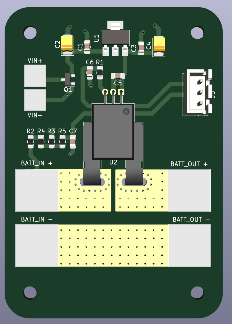
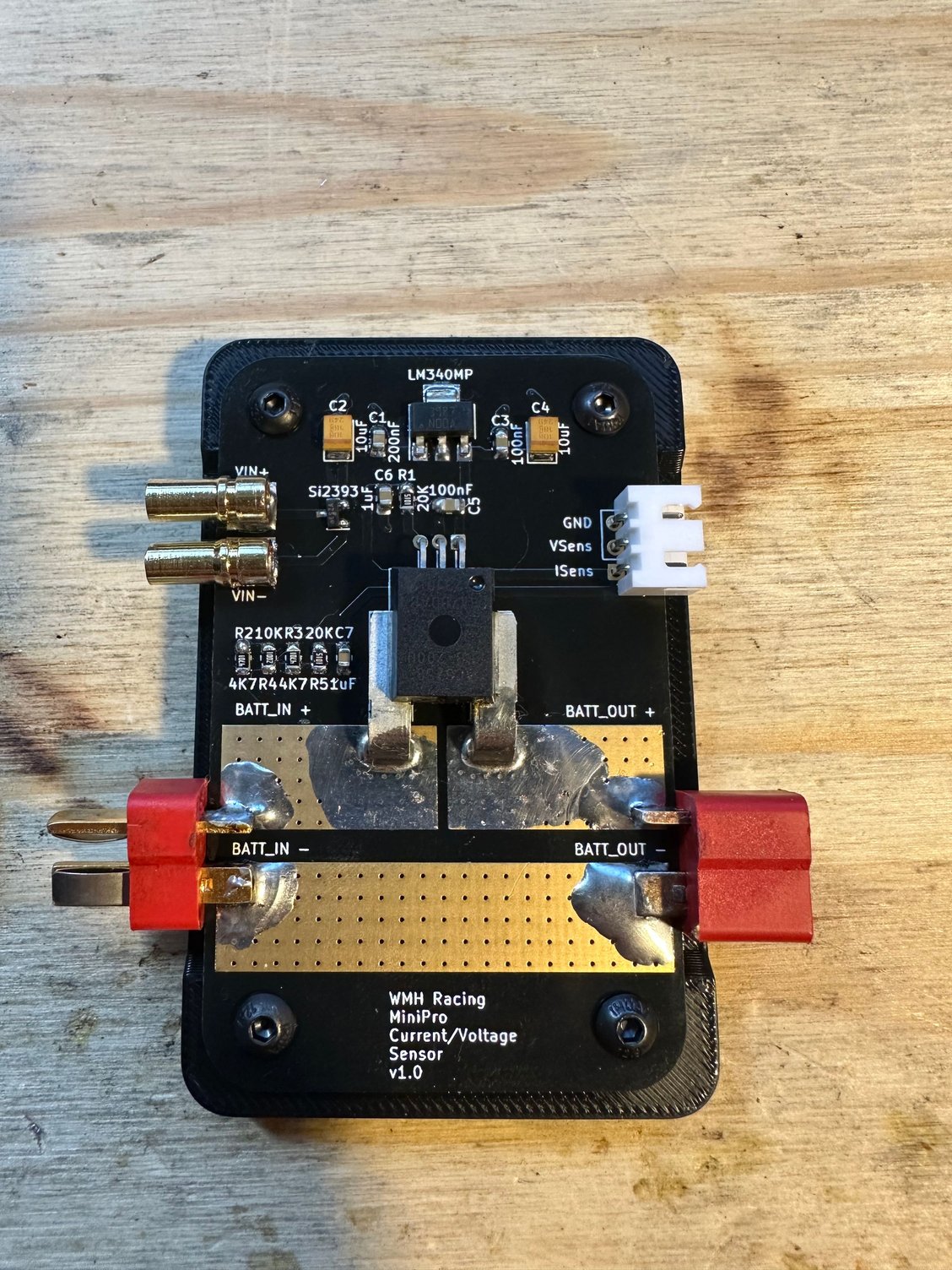
Here is a quick build... Slightly bigger than the MiniPro since I have all the components on the top of the board and a solid ground pour on the bottom, except where the positive battery trace for the main current lead. Those are on top and bottom and via stitched.
EDIT: This was just a quick assembly. I need to move the pads around a bit still. I think I want to use XT90 connectors on the battery input and outputs, so not sure if I want to use the standard XT90s or use the PWs which require different pads. VIN can be 7-15V, but I think it would be best to use a 2s battery to power the board. Not sure how hot the regulator will get reducing 12V down to 5V.
EDIT: This was just a quick assembly. I need to move the pads around a bit still. I think I want to use XT90 connectors on the battery input and outputs, so not sure if I want to use the standard XT90s or use the PWs which require different pads. VIN can be 7-15V, but I think it would be best to use a 2s battery to power the board. Not sure how hot the regulator will get reducing 12V down to 5V.
03-17-2024, 09:58 AM
#98
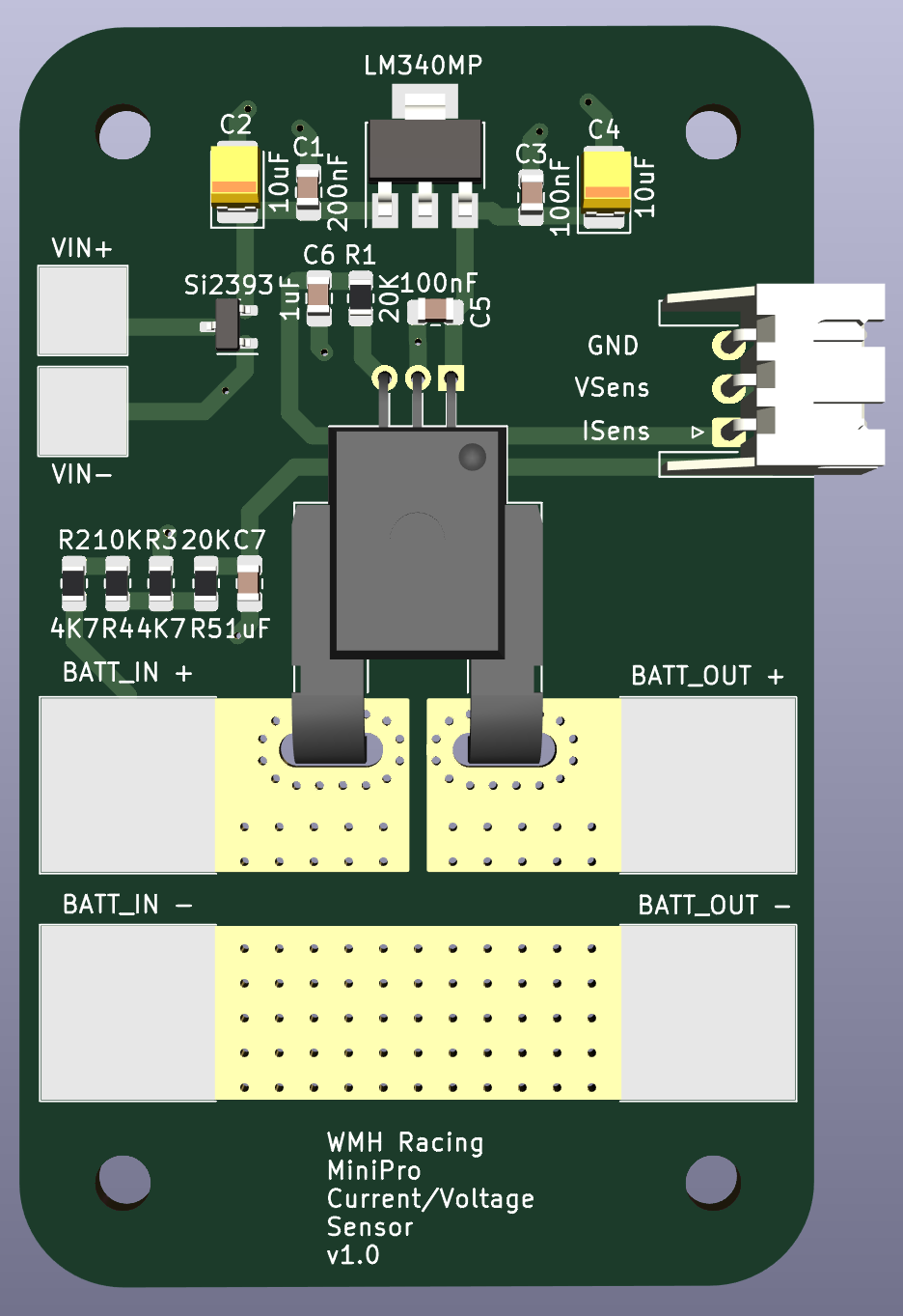
Here is an update to the board, changed the JST connector to a right angle, added all the component values, moved the pads a bit. I am going to order 10 of these, since an extra 5 is only a couple of dollars more than 5, and it is always nice to have current sensors... Using 2oz copper pours makes the boards slightly more expensive, but if someone wants the gerber, let me know. Board size is ~ 50mm x 80mm, so it is bigger than the MiniPro. I used the same value components MiniPro used for the RC filter and the voltage dividers for the voltage sensing. I did add an RC filter on the voltage sense though. To be honest, the filters really aren't needed because it will be full throttle pulls, but they won't hurt anything being there. And worst case you remove the resistor and capacitor, thent add a 0 ohm resistor in its place and leave the capacitor off...
 03-18-2024, 08:48 AM
#99
Looks pretty good. Your filter on the current has a cutoff frequency of about 8 Hz which is really low. You might get some weird results due to the phase shift of the current. I would go a little higher like 50 or 100Hz.
Do you have a schematic that we could see? I am curious as to why you are using Q1.
I think your voltage regulator will be ok running on 12V especially if there is a plane in the board attached to the tab of the device.
Do you have a schematic that we could see? I am curious as to why you are using Q1.
I think your voltage regulator will be ok running on 12V especially if there is a plane in the board attached to the tab of the device.
03-18-2024, 09:20 AM
#100
Looks pretty good. Your filter on the current has a cutoff frequency of about 8 Hz which is really low. You might get some weird results due to the phase shift of the current. I would go a little higher like 50 or 100Hz.
Do you have a schematic that we could see? I am curious as to why you are using Q1.
I think your voltage regulator will be ok running on 12V especially if there is a plane in the board attached to the tab of the device.
Do you have a schematic that we could see? I am curious as to why you are using Q1.
I think your voltage regulator will be ok running on 12V especially if there is a plane in the board attached to the tab of the device.
Q1 is a p-channel mosfet used for reverse polarity protection. It is my standard goto to add reverse polarity protection for the power source.
03-18-2024, 02:32 PM
#101
The RC filter is just using the same components that the MiniPro does on their board. Considering that most esc use at least a 1k pwm frequency, yes it is low. Somewhere around 300Hz would be fine, but like I said, just using their values. And really the filter is only there for partial throttle pulls since at full throttle it will be 100% duty cycle. But regardless, there are no issues with their component choice for their filter...
Q1 is a p-channel mosfet used for reverse polarity protection. It is my standard goto to add reverse polarity protection for the power source.
Q1 is a p-channel mosfet used for reverse polarity protection. It is my standard goto to add reverse polarity protection for the power source.
03-18-2024, 03:35 PM
#102
I don't think a phase shift will be an issue, the goal is to make a DC line. Rise time, well I guess you can make the argument that it will respond a little too slow. But the good news is, I have lots of capacitors and resistors to try different values.
03-22-2024, 05:22 PM
#103
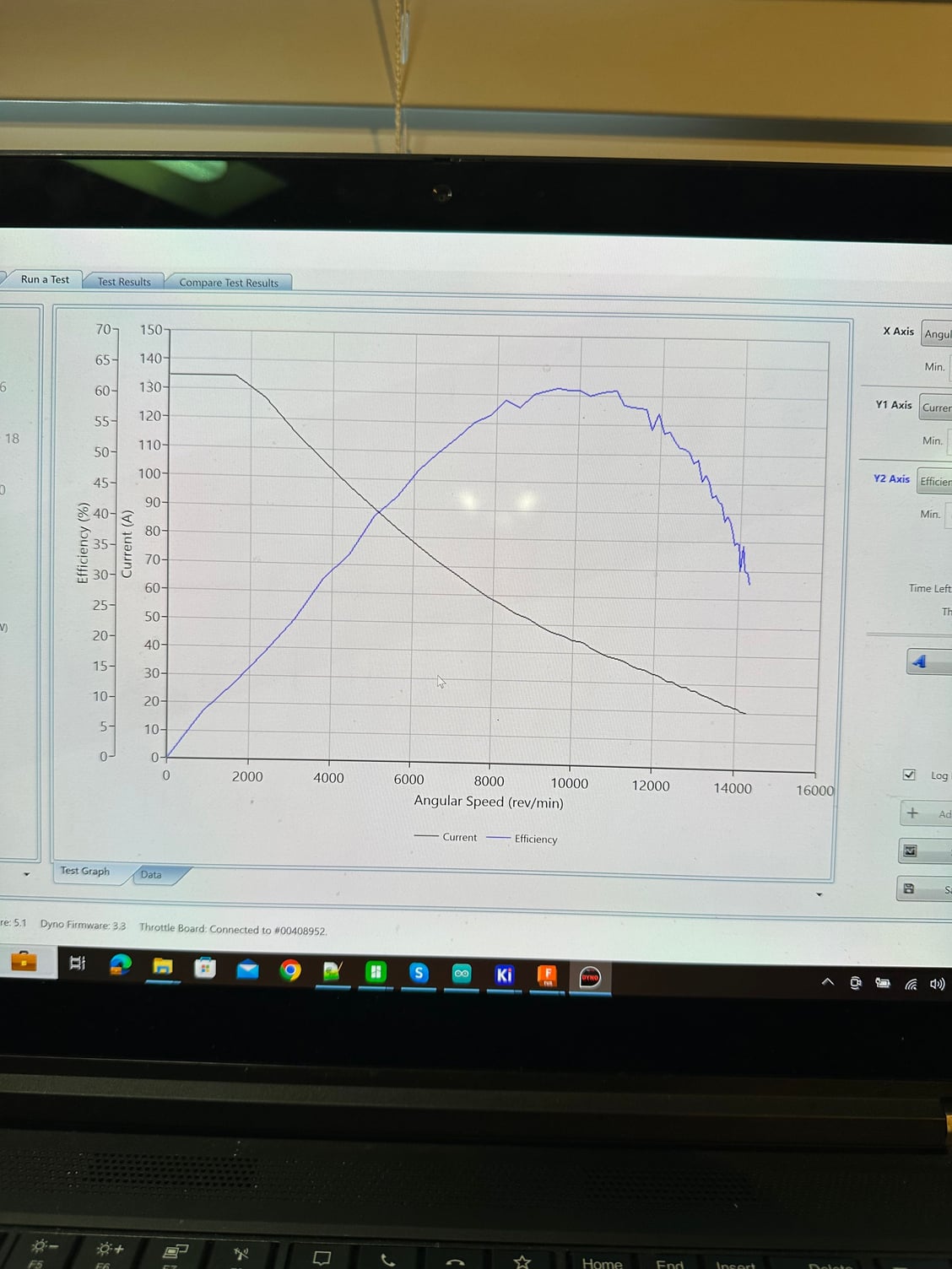
PCBs came in for my current sensor. Got one out together and did a test with it. Finally, I get usable current results which gives realistic efficiency numbers. This has been almost a year long struggle to get good efficiency. Mind you I didn�t dedicate a ton of time, it just took forever. Now to fix some software issues with the v3 board�
03-22-2024, 09:01 PM
#104
So when can we buy this device? Also, when we can buy it, can we have the option of no pre-installed connectors?