


 11Likes
My $100 homebuilt RC motor power dyno
 12-14-2020, 04:49 AM
#1
Tech Rookie
Thread Starter
Hi, guys
Here is a small project that I had started last winter and that I had put aside during summer.... In November, during our second lock down (I live in France) I spent some time to finish it, test it and make a small video to summarize how it works and how it’s made.
Part 1
It is a homebuilt RC motor dyno

It cost me a little over $100 but of course, many hours of research, thinking and testing
All it takes is full throttle acceleration to maximum rpm, to be able to calculate and plot all the curves for torque, mechanical power, amperage, voltage, therefore electric power, and therefore also efficiency, and temperature.
Here is the vid:
The motor drives an inertia flywheel (the bench grinder rotor + the damper pulley).
An infrared sensor (hidden by the casing) measures its speed, there is also a voltmeter, and an ammeter in the small black box between the battery and the ESC .
A temperature sensor wrapped around the engine to provides live motor temperature reading.
Then in the big black box we have an Arduino uno (a microcontroller) which is used to read the values of all the sensors several hundred times per second and sends them in packets to the laptop.
On the laptop I use the great Simpledyno software (software developed by DamoRC ) to calculates and plot the test result curves .
On this same black box I added a LCD screen which displays directly flywheel rpm (without the laptop), it was needed for safety during initial dyno testing but it is not mandatory as everything can be displayed in real time by the laptop on the SimpleDyno dashboard.
What is crucial for this type of dyno, is to have absolutely no slippage (slipper prohibited) because all the engine power must pass through the flywheel to have a true and accurate torque and power measurement.
My vid is from my first testing campaign, where I used an old 13.5T, to start playing with engine timing, boost (angle, start rpm, end rpm) and turbo (angle, start rpm).
It is quiet easy to hunt for peak power, but instead I prefer to try finding useable power (wide powerband)… I try increasing low end power and keep the power curve as rounded as possible.
Another important point is to keep the efficiency as high as possible. Anything that isn't turned into mechanical watts is turned into heat.
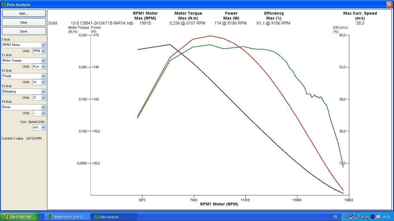
As an example, in the graph above, this old 13.5T is set with 5 � initial (motor end bell) the boost starts at 2k rpm until reaching 41 � at 10k rpm (46 � total) and at 9k rpm the turbo comes in and add another 15 � more ... (its a test, not a recommended setting )
)
I haven’t invented anything new here... inertia dyno exists for decades but for my RC motors, I didn't have $700 to spend for a MiniPro dyno that does all this certainly very well... but with motivation, perseverance, and knowledge available everywhere on the Internet, It’s fun to make stuff...
Nicolas
Here is a small project that I had started last winter and that I had put aside during summer.... In November, during our second lock down (I live in France) I spent some time to finish it, test it and make a small video to summarize how it works and how it’s made.
Part 1
It is a homebuilt RC motor dyno
It cost me a little over $100 but of course, many hours of research, thinking and testing
All it takes is full throttle acceleration to maximum rpm, to be able to calculate and plot all the curves for torque, mechanical power, amperage, voltage, therefore electric power, and therefore also efficiency, and temperature.
Here is the vid:
The motor drives an inertia flywheel (the bench grinder rotor + the damper pulley).
An infrared sensor (hidden by the casing) measures its speed, there is also a voltmeter, and an ammeter in the small black box between the battery and the ESC .
A temperature sensor wrapped around the engine to provides live motor temperature reading.
Then in the big black box we have an Arduino uno (a microcontroller) which is used to read the values of all the sensors several hundred times per second and sends them in packets to the laptop.
On the laptop I use the great Simpledyno software (software developed by DamoRC ) to calculates and plot the test result curves .
On this same black box I added a LCD screen which displays directly flywheel rpm (without the laptop), it was needed for safety during initial dyno testing but it is not mandatory as everything can be displayed in real time by the laptop on the SimpleDyno dashboard.
What is crucial for this type of dyno, is to have absolutely no slippage (slipper prohibited) because all the engine power must pass through the flywheel to have a true and accurate torque and power measurement.
My vid is from my first testing campaign, where I used an old 13.5T, to start playing with engine timing, boost (angle, start rpm, end rpm) and turbo (angle, start rpm).
It is quiet easy to hunt for peak power, but instead I prefer to try finding useable power (wide powerband)… I try increasing low end power and keep the power curve as rounded as possible.
Another important point is to keep the efficiency as high as possible. Anything that isn't turned into mechanical watts is turned into heat.
As an example, in the graph above, this old 13.5T is set with 5 � initial (motor end bell) the boost starts at 2k rpm until reaching 41 � at 10k rpm (46 � total) and at 9k rpm the turbo comes in and add another 15 � more ... (its a test, not a recommended setting
)I haven’t invented anything new here... inertia dyno exists for decades but for my RC motors, I didn't have $700 to spend for a MiniPro dyno that does all this certainly very well... but with motivation, perseverance, and knowledge available everywhere on the Internet, It’s fun to make stuff...
Nicolas
Last edited by widefive63; 12-16-2020 at 01:49 PM. Reason: part title
 12-14-2020, 08:09 AM
#2
Tech Adept
Great stuff!
Would it be possible to get a detailed write-up on your build.
Would it be possible to get a detailed write-up on your build.
12-14-2020, 09:26 AM
#3
Tech Rookie
That's really cool. Would you be willing to do a bunch of timing testing? There seems to be a shortage of real information about timing effects with empirical evidence.
 12-14-2020, 11:49 AM
#5
Tech Rookie
Thread Starter
I will do my best in the coming posts to provide you with some guidelines and advises for such project:
Part 2
A preliminary advice may be to read and watch all you can find on the topic and in fact and there is a lot of things on this dyno topic on the web, (car, motorcycle, karting or RC)
But the very first real advice is SAFETY FIRST
Even if it is designed to measure power on a small 540 RC motor, the energy stored in such small dyno can be very dangerous and mechanical failure (flywheel explosion...) can lead very serious injuries.
That said, here is the first few Q&A attempt:
Brake dyno or inertia dyno ?
Brake dyno are very complex to build and to adjust and especially useful for tuning carbs at a fixed speed. No very useful for our electric motors...
Inertia dynos are much easier to design and give you in few second run all the curves you need : torque, mechanical power, current, voltage, therefore in coming power, therefore also efficiency, and temperature if you want.
Rolling dyno or motor dyno?
To be useful it must be accurate or at least repeatable. Two run of the same motor should give the same result.
And the way we calculate the power with an inertial bench, absolutely no slippage is authorized.
So we can forget rolling dyno because of tires slippage or trans slippers . The only practical solution to measure motor power on an inertia dyno is to measure the engine alone and connect it to the flywheel with a direct shaft or with positive transmission ( pignon, chain, toothed belt)
Direct flywheel drive or reduction transmission?
The direct shaft transmission is ideal regarding losses but it rises some serious safety concern...
Do you really want to play with a 30000 rpm flywheel in your living room? Not me.
This is why I have chosen a gear transmission, 5 to 1 ratio to keep flywheel speed under 6000 rpm even with low turn motor.
The downside of this design is the loss induced by these gears. It will distor (lower) your torque and power reading. However the good news is that these losses are mostly repeatable, and even if the absolute power reading will be a little off, the relative reading between two dyno pull with different motors or two motor setting will be exploitable for our tuning purpose.
Why a bench grinder and an automotive engine damper pulley?
They are both already intended for high rev. and they are cheap...
Small bench grinder are very good candidate for such dyno as they already have bearings, They are generally limited to 3000 rpm because of grindstone explosion risk, but they can spin at higher speed. The stator is heavy (good to avoid vibrations) The rotor is already balanced. However the rotor is not very heavy,alone it doesn't provide enough inertia. But good news you can add more inertia, thank to the 1/2 inch (12,7mm ) shaft ends.
If you have access to a lathe you can make yourself an additional flywheel, but that was not my case. So after searching I found this solution...a damper pulley 12,5mm inner diameter, already balanced and high rev friendly. After some inertia mesurement I discarded the outer grooved rim to reduce the inertia within my inertia target.
Nicolas
To be continued soon....
Last edited by widefive63; 12-16-2020 at 01:48 PM. Reason: Part title
12-14-2020, 12:49 PM
#6
Tech Adept
Thanks very much. I appreciate your time and effort.
12-14-2020, 08:14 PM
#7
I use simple dyno also, but a flywheel that I built myself. Instead of infrared RPM sensing, I use a neodymium magnet with hall effect sensor. I also use a dedicated current sensor and voltage sensor. At one point, to sense voltage, I used a DIY voltage divider to measure it. But then changed it to dedicated one, and the accuracy increased..
Like yourself, I attempted to build my own version of the miniPro, but found that there were too many variables that affect the results of the dyno test. After two designs, switched to an MD2 flywheel setup where I cut my own flywheel out of wood. While dyno testing, I cover the flywheel with a box/crate as a safeguard to catch the flywheel and prevent it from flying thru the window..
The idea of the bench grinder is a good one. Nice job.
12-15-2020, 10:23 AM
#8
Tech Rookie
Thread Starter
I use simple dyno also, but a flywheel that I built myself. Instead of infrared RPM sensing, I use a neodymium magnet with hall effect sensor. I also use a dedicated current sensor and voltage sensor. At one point, to sense voltage, I used a DIY voltage divider to measure it. But then changed it to dedicated one, and the accuracy increased..
Like yourself, I attempted to build my own version of the miniPro, but found that there were too many variables that affect the results of the dyno test. After two designs, switched to an MD2 flywheel setup where I cut my own flywheel out of wood. While dyno testing, I cover the flywheel with a box/crate as a safeguard to catch the flywheel and prevent it from flying thru the window..
The idea of the bench grinder is a good one. Nice job.
Like yourself, I attempted to build my own version of the miniPro, but found that there were too many variables that affect the results of the dyno test. After two designs, switched to an MD2 flywheel setup where I cut my own flywheel out of wood. While dyno testing, I cover the flywheel with a box/crate as a safeguard to catch the flywheel and prevent it from flying thru the window..
The idea of the bench grinder is a good one. Nice job.
Hi MaxRain,
To my understanding you run 17,5t motors , for which the MD2 dyno is perfect.
Concerning your wood flywheel, did you have any balancing issue? what is your average dyno run time to reach max rpm with your 17,5?
My first idea was also to use the Eagle MD2 approach (flywheel fixed to the motor shaft) but the flywheel inertia is too low for low turn motors... It is to low to test anything under 13,5t... my needs are mainly in the 9,5t to 6,5t range (1/10 carpet off road)
And making an heavier flywheel might have been too dangerous for the motor shaft and bearing.
I have taken a look at your electric karting project on youtube.. Very very impressive.

Last edited by widefive63; 12-15-2020 at 12:03 PM.
12-15-2020, 11:08 AM
#9
Hi MaxRain,
To my understanding you run 17,5t motors , for which the MD2 dyno is perfect.
Concerning your wood flywheel, how did you have any balancing issue? what I you average dyno run time to reach max rpm with your 17,5?
My first idea was also to use the Eagle MD2 approach (flywheel fixed to the motor shaft) but the flywheel inertia is too low for low turn motors... It is to low to test anything under 13,5t... my needs are mainly in the 9,5t to 6,5t range (1/10 carpet off road)
And making an heavier flywheel might have been too dangerous for the motor shaft and bearing.
I have taken a look at your electric karting project on youtube.. Very very impressive.
This is the most difficult part, and crucial for the dyno to operate accurately. If the flywheel is unbalanced, then it has a much higher chance of dislodging from the shaft/rotor.
As for length of time a 17.5 turn motor takes to spool up, its approximately 4 - 5 seconds.
Note: I usually test at lower voltages, typically 7.6v for safer testing speeds.
As for the karting project, not me..
12-15-2020, 09:01 PM
#10
Tech Master
This is awesome! You seem pretty set in some of the evaluations you have made and my intentions are to congratulate you for a significant accomplishment.
I would challenge some of your evaluations (professionally and not personal) if you have a mind to hear alternative information.
Either way I�m happy for your creation and abilities.
I would challenge some of your evaluations (professionally and not personal) if you have a mind to hear alternative information.
Either way I�m happy for your creation and abilities.
12-16-2020, 01:42 AM
#11
Tech Rookie
Thread Starter
This is awesome! You seem pretty set in some of the evaluations you have made and my intentions are to congratulate you for a significant accomplishment.
I would challenge some of your evaluations (professionally and not personal) if you have a mind to hear alternative information.
Either way I�m happy for your creation and abilities.
I would challenge some of your evaluations (professionally and not personal) if you have a mind to hear alternative information.
Either way I�m happy for your creation and abilities.
Thanks for these kind words... I will be very pleased to discuss with you any technical point of this project, that I still consider as a work in progress.
Nicolas
12-16-2020, 10:26 AM
#12
Wonderful job you've done. I have a Minipro, and this is electronically similar to it's design. But I have to question how you calculated the rotational mass of your flywheel. It's pretty easy when it's a solid piece of metal, but you've got difference diameters, metals, etc.
12-16-2020, 01:26 PM
#13
Tech Rookie
Thread Starter
Part 3
How much inertia should my flywheel have?
That is certainly the toughest question when starting such a project..
If the inertia is too low for your motor, the full throttle acceleration phase will be too short and your computer will not be able to record enough points to obtain a clean curve.
If the inertia is too high (very high) there is a risk of burning the motor...
Electric motors have their peak torque when leaving the static position...and current and torque are almost proportional. So when you leave this static position and you are at full throttle your motor will see very high current. You can expect values in the 50/100 amps range and your motor cannot withstand this punishment too long....
Depending on the performance of your data recording system, a run time from 5 to 10s might be a good starting point
Ok now lets talk inertia numbers....
Before starting this project I had no clue of how much inertia was needed. So I tried to benchmark data available here and there, and for this Minipro website is a real gold mine.... by crossing these data I was able to build the following table:
Motor: Moment of inertia (seen by the motor)
2.5t to 6.5t 13 kgmm2
6.5t to 13.5t 49 kgmm2
13.5t to 17.5t 177 kgmm2
17.5t to 21.5t 211 kgmm2
21.5t and up 500 kgmm2
I found also some data on the Eagle racing MD2 dyno
Motor: Moment of inertia (flywheel)
13.5t and up 24 kgmm2
As you see both table are not really comparable but at least we have a ballpark...
My opinion (no fact here) is that on both dyno the inertia has been capped for mechanical reason, on MiniPro for increasing life of the tooth belt and on the MD2 to prevent bending the 3,175mm shaft is case of slight flywheel imbalance....
So we can start designing our flywheel?
Yes almost ...Before that I recommend to spend some time reading some sort of � Moment of inertia 101 � articles to have an overview of the technical direction to follow. And if you are not found of maths and physics, on the web you will find hundreds of � Moment of inertia calculator � that will help you test your concept dimensions and feasibility....
Important: If you plan to use any form of gear reduction between your motor and the flywheel (like the Minipro or like mine) you will have to become familiar with the rules of � projected Inertia � ....
To be short, in that case the inertia seen by the motor will be the flywheel inertia divided by the gear ratio squared.
As an example my dyno flywheel current inertia is 6060 kgmm2... but because of the 5 to 1 gear reduction, you have to divide this inertia by 25 to get the projected inertia of 242 kgmm2 seen by the motor...
One last word about moment of inertia for today...
The accuracy of the dyno is very dependent of the accuracy of your inertia input.
If you have already tried to calculate moment of inertia of a real flywheel you will find that beside being very boring, there are also shapes for which there will be no simple formula... and what to do with bearings, screws... and what about friction?...
You will be certainly happy to know that there is a very simple method to measure the moment of inertia of your dyno with
a few steel shims,
a piece sewing thread
and a mobile phone....
More on that in next episode..
(spoiler alert: there is a clue at the end of the vid featured in part 1)
Nicolas
To be continued...
Last edited by widefive63; 12-16-2020 at 03:29 PM. Reason: table display
12-16-2020, 01:32 PM
#14
Tech Rookie
Thread Starter
Wonderful job you've done. I have a Minipro, and this is electronically similar to it's design. But I have to question how you calculated the rotational mass of your flywheel. It's pretty easy when it's a solid piece of metal, but you've got difference diameters, metals, etc.
As you will see in my today�s episode there is a very simple and accurate method that I will try to explain in detail in the next one ....
Stay tuned
Nicolas
12-16-2020, 09:18 PM
#15
Tech Master
1-
Brake dyno or inertia dyno ?
Brake dyno are very complex to build and to adjust and especially useful for tuning carbs at a fixed speed. No very useful for our electric motors...
Inertia dynos are much easier to design and give you in few second run all the curves you need : torque, mechanical power, current, voltage, therefore in coming power, therefore also efficiency, and temperature if you want.
2-
Rolling dyno or motor dyno?
To be useful it must be accurate or at least repeatable. Two run of the same motor should give the same result.
And the way we calculate the power with an inertial bench, absolutely no slippage is authorized.
So we can forget rolling dyno because of tires slippage or trans slippers . The only practical solution to measure motor power on an inertia dyno is to measure the engine alone and connect it to the flywheel with a direct shaft or with positive transmission ( pignon, chain, toothed belt)
3-
Direct flywheel drive or reduction transmission?
The direct shaft transmission is ideal regarding losses but it rises some serious safety concern...
Do you really want to play with a 30000 rpm flywheel in your living room? Not me.
This is why I have chosen a gear transmission, 5 to 1 ratio to keep flywheel speed under 6000 rpm even with low turn motor.
The downside of this design is the loss induced by these gears. It will distor (lower) your torque and power reading. However the good news is that these losses are mostly repeatable, and even if the absolute power reading will be a little off, the relative reading between two dyno pull with different motors or two motor setting will be exploitable for our tuning purpose.
3-
Why a bench grinder and an automotive engine damper pulley?
They are both already intended for high rev. and they are cheap...
Small bench grinder are very good candidate for such dyno as they already have bearings, They are generally limited to 3000 rpm because of grindstone explosion risk, but they can spin at higher speed. The stator is heavy (good to avoid vibrations) The rotor is already balanced. However the rotor is not very heavy,alone it doesn't provide enough inertia. But good news you can add more inertia, thank to the 1/2 inch (12,7mm ) shaft ends.
If you have access to a lathe you can make yourself an additional flywheel, but that was not my case. So after searching I found this solution...a damper pulley 12,5mm inner diameter, already balanced and high rev friendly. After some inertia mesurement I discarded the outer grooved rim to reduce the inertia within my inertia target.
Nicolas
To be continued soon....
Heat is the opposite of power and its on a curve. the ratio of heat to power is small at peak power and larger everywhere else. Heat isn�t an issue for 1 pull but heat is stops you dead in your tracks or minimizes the amount of power you can deliver over an entire race. A brake dyno for a combustion engine is not testing the impact heat has on power or duration. A brake dyno for an electric motor is.
your bench grinder can be the perfect inertia and brake dyno. do something to convert the back emf from the motor into heat and then do it in a way that you know the watts of resistance its providing and you can use this to simulate being on chassis or you can use it to calculate the amount of heat your brushless motor can dissipate over a 5 minute race. (before it overheats). does the bench grinder have brushes? probably not but the torque a brushless motor delivers in the form of resistance (load dyno) is linear and predictable.
the ratio of rotor inertia to load inertia primarily drives braking effectiveness when you aren�t using it to calculate power.
2-rolling dyno or motor dyno-these brushless motor and esc only manage 1 variable by design. PWM. PWM induces torque. torque has a by product of speed but they are only connected to each other when all the other physics are held constant. if any variable changes the ratio of torque to speed changes. Specifically a power curve expands or contracts depending on how much torque is being consumed. you can apply this compression factor to a motor dyno and figure out what you curve looks like on chassis but 1 will have 20k rpm and the other will have 10k for example. it is possible to minimize slippage on a chassis dyno. (I do it)
3-torque transmission. You know the math around inertia so I�m assuming you can figure out how to calculate losses from gear efficiencies. it is expressed in terms of torque. if you hang 1 lb at 1 foot off the center of you gear train you can adjust your torque numbers to be absolute. A ftlb is too much but you can add weight at what er distance you want and when the motor input shaft starts to move you will know the torque loss over the rpm of a power measurement run.
it takes about 10 seconds for the mini pro to go from 0 to full rpm. add rotational mass until it takes about 10 seconds.
dont take me wrong. Most people dont understand what a dyno does and couldn�t build one if they wanted to. What you have built will provide you with some very good information. what I�m describing may not feel right to some people because RC cars are so similar to full size race cars and you do get great data when you build something that works like a combustion engine dyno. There is more data you can get that helps you maximize the not so well known degrees of freedom and restriction when squeezing power out of an electric motor.