


LeMans LMP1: 200mm Pan Class Discussion
 06-10-2014, 01:09 PM
#301

No, These: http://www.bocabearings.com/bearing-...103zz53175bore for $31.95 a 4 pack. Pricey, but not too insanely pricey.
 06-10-2014, 02:08 PM
#302
No, These: http://www.bocabearings.com/bearing-...103zz53175bore for $31.95 a 4 pack. Pricey, but not too insanely pricey.
06-13-2014, 12:29 PM
#304
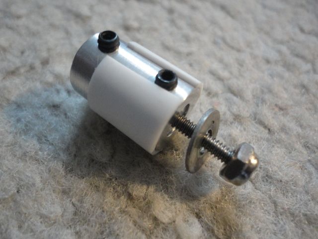
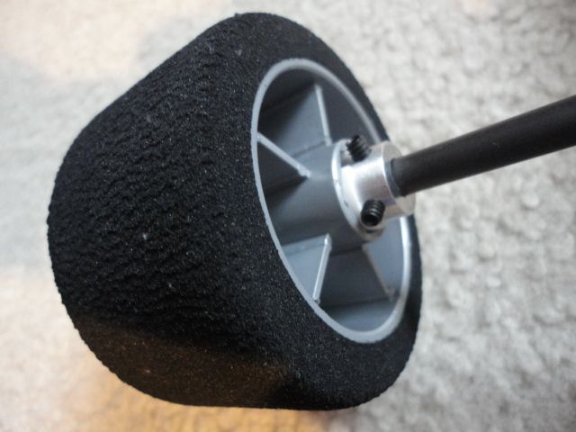
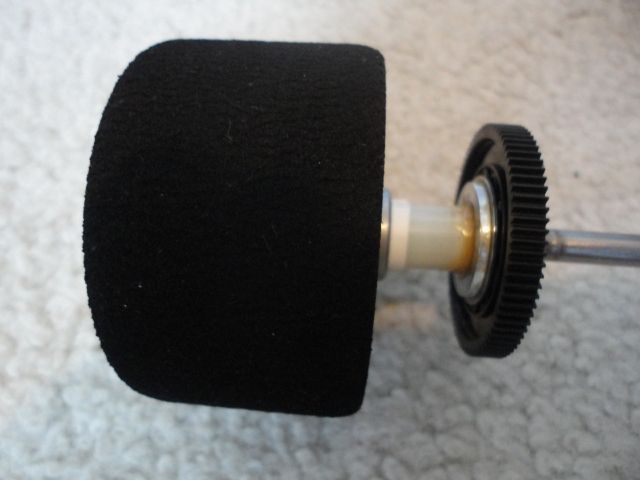
Here's how I adapted the live side (left side on most cars) of my WGT rear axle to accept the Speed Passion LM1 rear tires/wheels, #SP000991.
The main item is a 1/4" shaft coupler. I used one made of aluminum, having an OD of 1/2" and a length of 3/4". It has two set screws at right angles to each other on each end to eliminate wobble.
The coupler OD is not large enough to give a good fit into the 14mm hex on the wheel, so I built it up using a sleeve cut from 1/2" OD styrene tube with 0.028" wall thickess (Evergreen Scale Models #436). The tube is split lengthwise to allow it to slide over the coupler and clear the coupler's set screw, used to secure the stud (more on this below). It's easy to cut the sleeve squarely by starting with an excess length slid over the coupler, then using the edge of the coupler as a guide for a razor blade.
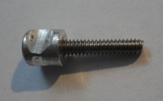
The rules require a single nut to secure the wheel, so I made a stud to fit the coupler, using a 4-40 screw about 3/4" long and a 4-40 aluminum standoff with 1/4" OD and 1/4" length (Keystone Electronics #3478). I threaded the screw into the standoff, then cut off the head flush with the standoff using a Dremel cutoff wheel. A small drop of cyanoacrylate on each side secures the screw threads permanently into the standoff.
The standoff requires a flat for the coupler's set screw. I used the Dremel and cutoff wheel to make a flat of about the width of the set screw, but leaving a lip on each side to keep the stud from pulling out of the coupler when the wheel nut is tightened. If you are using a coupler with two set screws on each end, then the flat needs to be deep enough that the set screw doesn't protrude past the OD of the coupler when torqued down. The other set screw fits into the split in the plastic sleeve, and DOES need to protrude from the coupler by about 0.040" to 0.050", as it will fit into the "point" of the wheel hex to serve as an anti-rotation feature.
A 4-40 locknut and a washer with about a 7/16" OD secures the wheel to the assembly. (The washer is necessary if the wheel's center hole has been reamed or drilled to clear the thrust bearing for use on the diff side.)
The axle will need to be cut to length to keep the total width across the wheels within the class specifications, and within the body. Leave enough room to add axle shims to get the wheels centered with respect to the chassis. I added a couple of small flats to the axle for the coupler set screws, then coated the flat section with a thin layer of cyanoacrylate for reinforcement. I recommend that the ends of the set screws be ground flat, or that they be replaced with regular screws with flat ends, as the normal cup point will destroy a graphite axle.
This is certainly not the only way to adapt a WGT to accept these tires and wheels, and it's not necessarily the most cost effective, either. (For instance, if you already have a complete axle assembly from an F1 car available, then use it!) Some of you may be able to scrounge up a number of the required parts from the junk bin, or from random stuff laying around the house. For instance, the small end of a tube of chapstick is about the right size for the plastic sleeve.
Other ideas: I think a good alternative to the above is possible if you already have a hex axle hub from an F1 car. These usually use a 6mm axle, so it requires either drilling out the hub to 1/4" ID to fit the pan car axle (which is difficult to do accurately enough to prevent wobble) or turning down the end of the 1/4" axle to fit the hub. The second option sounds possible, at least for a graphite axle, by spinning it up and carefully dressing the axle OD with a fine, flat file until the hub just slides on. (This will, of course, prevent going back to the original pan car hub.) I haven't attempted this, though, so try it at your own risk!
SOURCES:
1/4" Shaft Coupler:
http://www.ebay.com/itm/1-4-INCH-SHA...item3a8ed7d5bc
Plastic Tube:
http://www3.towerhobbies.com/cgi-bin...?&I=LXCRLY&P=7
Standoff:
http://www.mouser.com/ProductDetail/...VQ1sLz%2fA0%3d
The main item is a 1/4" shaft coupler. I used one made of aluminum, having an OD of 1/2" and a length of 3/4". It has two set screws at right angles to each other on each end to eliminate wobble.
The coupler OD is not large enough to give a good fit into the 14mm hex on the wheel, so I built it up using a sleeve cut from 1/2" OD styrene tube with 0.028" wall thickess (Evergreen Scale Models #436). The tube is split lengthwise to allow it to slide over the coupler and clear the coupler's set screw, used to secure the stud (more on this below). It's easy to cut the sleeve squarely by starting with an excess length slid over the coupler, then using the edge of the coupler as a guide for a razor blade.
The rules require a single nut to secure the wheel, so I made a stud to fit the coupler, using a 4-40 screw about 3/4" long and a 4-40 aluminum standoff with 1/4" OD and 1/4" length (Keystone Electronics #3478). I threaded the screw into the standoff, then cut off the head flush with the standoff using a Dremel cutoff wheel. A small drop of cyanoacrylate on each side secures the screw threads permanently into the standoff.
The standoff requires a flat for the coupler's set screw. I used the Dremel and cutoff wheel to make a flat of about the width of the set screw, but leaving a lip on each side to keep the stud from pulling out of the coupler when the wheel nut is tightened. If you are using a coupler with two set screws on each end, then the flat needs to be deep enough that the set screw doesn't protrude past the OD of the coupler when torqued down. The other set screw fits into the split in the plastic sleeve, and DOES need to protrude from the coupler by about 0.040" to 0.050", as it will fit into the "point" of the wheel hex to serve as an anti-rotation feature.
A 4-40 locknut and a washer with about a 7/16" OD secures the wheel to the assembly. (The washer is necessary if the wheel's center hole has been reamed or drilled to clear the thrust bearing for use on the diff side.)
The axle will need to be cut to length to keep the total width across the wheels within the class specifications, and within the body. Leave enough room to add axle shims to get the wheels centered with respect to the chassis. I added a couple of small flats to the axle for the coupler set screws, then coated the flat section with a thin layer of cyanoacrylate for reinforcement. I recommend that the ends of the set screws be ground flat, or that they be replaced with regular screws with flat ends, as the normal cup point will destroy a graphite axle.
This is certainly not the only way to adapt a WGT to accept these tires and wheels, and it's not necessarily the most cost effective, either. (For instance, if you already have a complete axle assembly from an F1 car available, then use it!) Some of you may be able to scrounge up a number of the required parts from the junk bin, or from random stuff laying around the house. For instance, the small end of a tube of chapstick is about the right size for the plastic sleeve.
Other ideas: I think a good alternative to the above is possible if you already have a hex axle hub from an F1 car. These usually use a 6mm axle, so it requires either drilling out the hub to 1/4" ID to fit the pan car axle (which is difficult to do accurately enough to prevent wobble) or turning down the end of the 1/4" axle to fit the hub. The second option sounds possible, at least for a graphite axle, by spinning it up and carefully dressing the axle OD with a fine, flat file until the hub just slides on. (This will, of course, prevent going back to the original pan car hub.) I haven't attempted this, though, so try it at your own risk!
SOURCES:
1/4" Shaft Coupler:
http://www.ebay.com/itm/1-4-INCH-SHA...item3a8ed7d5bc
Plastic Tube:
http://www3.towerhobbies.com/cgi-bin...?&I=LXCRLY&P=7
Standoff:
http://www.mouser.com/ProductDetail/...VQ1sLz%2fA0%3d
06-13-2014, 12:32 PM
#305
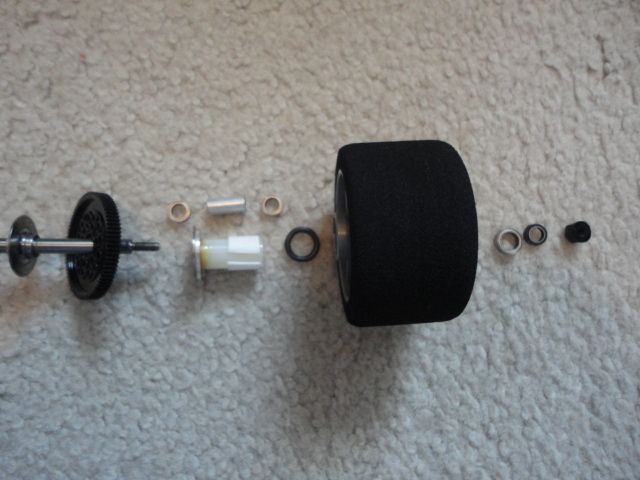
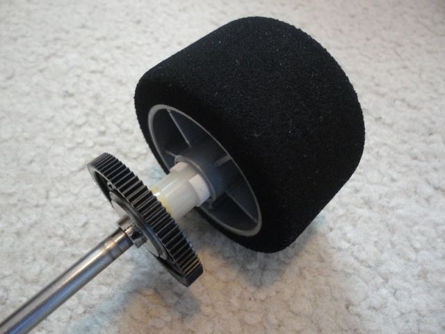
Here's how I adapted the differential side of my WGT rear axle to accept the Speed Passion LM1 rear tires/wheels, #SP000991. I used the original 1/4" diameter axle, which measures 1.59" from the seating surface for the differential ring to the end of the axle, not including the threaded stud. I believe this distance is standard for all 1/10 scale American pan car axles. The inner diff ring and spur gear from the original assembly are unchanged.
The first step is to ream or drill out the center hole in the Speed Passion wheel to clear the 1/4" axle. Make the hole a bit oversized so it will clear the axle even if it isn't centered perfectly.
The photo shows the order of the components. Starting closest to the centerline of the car and working our way out, there is the diff ring and spur gear (with its 1/4x3/8" support bearing, if your axle requires one) as used on the original axle assembly. Next is an RJ Speed Legends differential adapter (#5740) with one of their matching differential rings (#5752). If you prefer to use a D-style ring for its anti-rotation feature, or just because you already have it, you can modify the differential adapter with a Dremel cutoff wheel to accept it. Otherwise, a light film of Weldwood contact cement between the ring and adapter will prevent rotation, and keeps the ring in position during assembly.
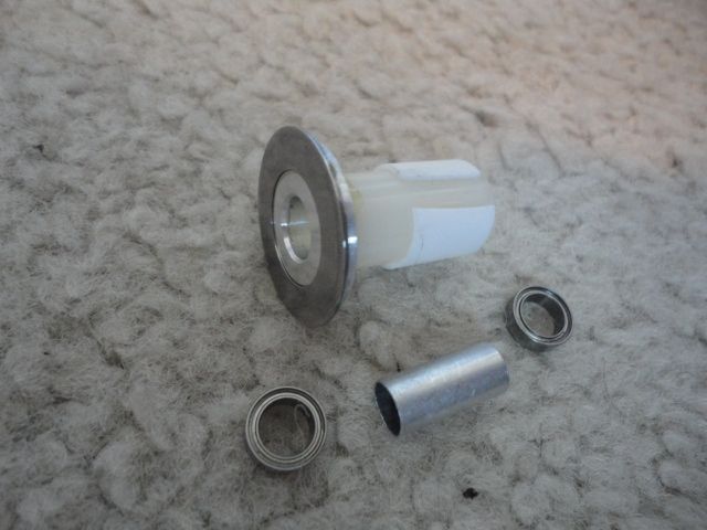
The differential adapter fits into a 3/8" ID x 1/2" OD x 1" long nylon spacer (see note, below.) Weldwood contact cement secures the differential adapter to the spacer, preventing rotation.
The spacer rides on two 1/4" ID x 3/8" OD x 1/8" wide ball bearings, with a 9/32" OD .014" Wall 0.62" long aluminum tube between them for positioning. NOTE: The Value Brand #13SPRT120 spacer has thin retaining ribs on one end of the spacer ID that must be removed with a reamer, drill, or razor blade before inserting the bearings. The Everbilt #87308 does not have the retaining ribs, but the inside ID is about 0.010" oversized, and requires some shimming to get the bearings to fit snugly (I used about two wraps of piece of paper).
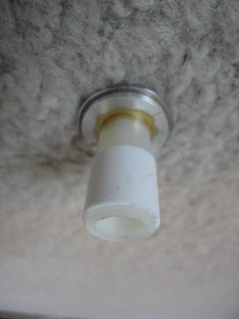
The spacer OD is not large enough to give a good fit into the 14mm hex on the wheel, so it is built up using a sleeve cut from 1/2" OD styrene tube with 0.028" wall thickess (Evergreen Scale Models #436). The tube is split lengthwise to allow it to slide over the coupler. A thin film of contact cement between the tube and the spacer holds it in place.
A 9/16" diameter O-ring with a 3/32" (Danco 96725) or 1/8" thickness interfaces the end of the spacer to the inside of the wheel. It transmits torque to the wheel and also serves as a compression member when tightening the differential adjustment nut.
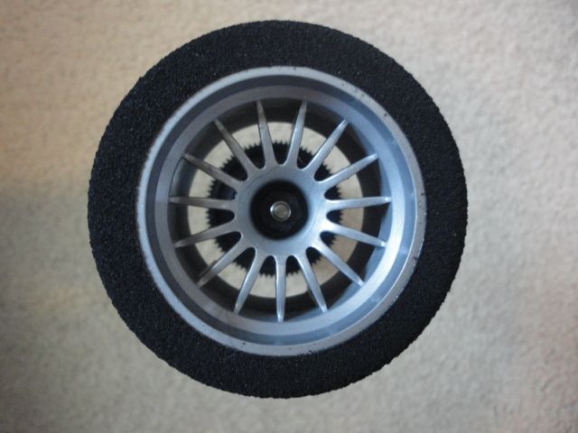
A 8mm ID x 12mm OD x 3.5mm W ball bearing fits into the outside opening of the wheel and serves as a thrust bearing. Although not a true thrust bearing, it is much more rugged than the 1/4" ID x 3/8" OD x 1/8" wide ball bearing used for this function on most pan car ball differentials.
Depending on the length of the axle, it may be possible to eliminate the original aluminum spacer that bears against the inner race of the thrust bearing. Also, the Belleville washers used to hold tension on the original assembly can be omitted, since the O-ring now serves this function. (This will make changing wheels a little faster, since there are fewer parts to drop on the floor!) My car required the aluminum spacer, and I left the washers in to make adjustment less sensitive.
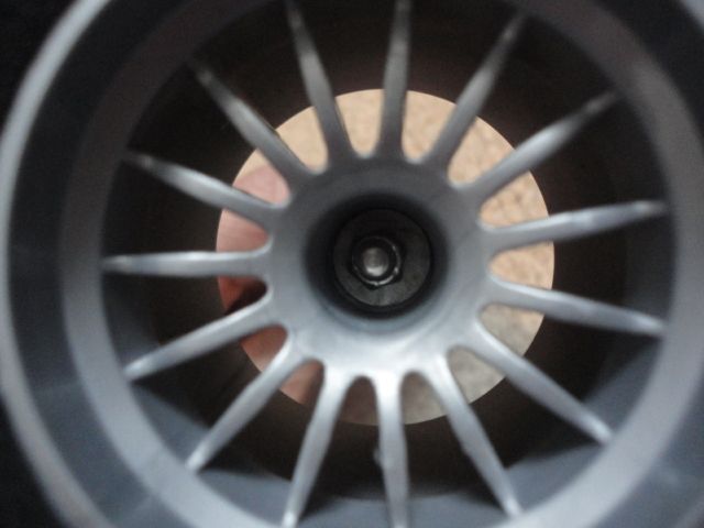
The 8-32 nylon locknut for setting the differential tension is a close fit into the Speed Passion wheel, so a thinwall socket or longnose pliers must be used to turn it.
This arrangement has about 2 to 3mm less offset than the original with BSR rear rims, so add axle shims to set the total car width to what you want.
SOURCES:
Differential Ring:
http://www3.towerhobbies.com/cgi-bin...?&I=LXYLJ9&P=7
Differential Adapter:
http://www3.towerhobbies.com/cgi-bin...?&I=LXAWBG&P=7
Nylon Spacer:
http://www.ebay.com/itm/Retaining-Sp...item4d19125bf8
OR
http://www.homedepot.com/p/Everbilt-...7308/100338254
Spacer Sleeve:
http://www3.towerhobbies.com/cgi-bin...?&I=LXCRLY&P=7
Hub Bearings:
http://www.avidrc.com/product/9/stan...-bearings.html
Bearing Spacer:
http://www3.towerhobbies.com/cgi-bin...?&I=LXAFV7&P=7
Drive O-Ring:
http://www.homedepot.com/p/Unbranded...4648/203574478
Thrust Bearing:
http://www.avidrc.com/product/1/bear...-bearings.html
The first step is to ream or drill out the center hole in the Speed Passion wheel to clear the 1/4" axle. Make the hole a bit oversized so it will clear the axle even if it isn't centered perfectly.
The photo shows the order of the components. Starting closest to the centerline of the car and working our way out, there is the diff ring and spur gear (with its 1/4x3/8" support bearing, if your axle requires one) as used on the original axle assembly. Next is an RJ Speed Legends differential adapter (#5740) with one of their matching differential rings (#5752). If you prefer to use a D-style ring for its anti-rotation feature, or just because you already have it, you can modify the differential adapter with a Dremel cutoff wheel to accept it. Otherwise, a light film of Weldwood contact cement between the ring and adapter will prevent rotation, and keeps the ring in position during assembly.
The differential adapter fits into a 3/8" ID x 1/2" OD x 1" long nylon spacer (see note, below.) Weldwood contact cement secures the differential adapter to the spacer, preventing rotation.
The spacer rides on two 1/4" ID x 3/8" OD x 1/8" wide ball bearings, with a 9/32" OD .014" Wall 0.62" long aluminum tube between them for positioning. NOTE: The Value Brand #13SPRT120 spacer has thin retaining ribs on one end of the spacer ID that must be removed with a reamer, drill, or razor blade before inserting the bearings. The Everbilt #87308 does not have the retaining ribs, but the inside ID is about 0.010" oversized, and requires some shimming to get the bearings to fit snugly (I used about two wraps of piece of paper).
The spacer OD is not large enough to give a good fit into the 14mm hex on the wheel, so it is built up using a sleeve cut from 1/2" OD styrene tube with 0.028" wall thickess (Evergreen Scale Models #436). The tube is split lengthwise to allow it to slide over the coupler. A thin film of contact cement between the tube and the spacer holds it in place.
A 9/16" diameter O-ring with a 3/32" (Danco 96725) or 1/8" thickness interfaces the end of the spacer to the inside of the wheel. It transmits torque to the wheel and also serves as a compression member when tightening the differential adjustment nut.
A 8mm ID x 12mm OD x 3.5mm W ball bearing fits into the outside opening of the wheel and serves as a thrust bearing. Although not a true thrust bearing, it is much more rugged than the 1/4" ID x 3/8" OD x 1/8" wide ball bearing used for this function on most pan car ball differentials.
Depending on the length of the axle, it may be possible to eliminate the original aluminum spacer that bears against the inner race of the thrust bearing. Also, the Belleville washers used to hold tension on the original assembly can be omitted, since the O-ring now serves this function. (This will make changing wheels a little faster, since there are fewer parts to drop on the floor!) My car required the aluminum spacer, and I left the washers in to make adjustment less sensitive.
The 8-32 nylon locknut for setting the differential tension is a close fit into the Speed Passion wheel, so a thinwall socket or longnose pliers must be used to turn it.
This arrangement has about 2 to 3mm less offset than the original with BSR rear rims, so add axle shims to set the total car width to what you want.
SOURCES:
Differential Ring:
http://www3.towerhobbies.com/cgi-bin...?&I=LXYLJ9&P=7
Differential Adapter:
http://www3.towerhobbies.com/cgi-bin...?&I=LXAWBG&P=7
Nylon Spacer:
http://www.ebay.com/itm/Retaining-Sp...item4d19125bf8
OR
http://www.homedepot.com/p/Everbilt-...7308/100338254
Spacer Sleeve:
http://www3.towerhobbies.com/cgi-bin...?&I=LXCRLY&P=7
Hub Bearings:
http://www.avidrc.com/product/9/stan...-bearings.html
Bearing Spacer:
http://www3.towerhobbies.com/cgi-bin...?&I=LXAFV7&P=7
Drive O-Ring:
http://www.homedepot.com/p/Unbranded...4648/203574478
Thrust Bearing:
http://www.avidrc.com/product/1/bear...-bearings.html
06-17-2014, 02:25 PM
#306
Has anyone tried to convert a HPI Formula 10 to LM1.
06-25-2014, 01:41 PM
#308
The LeMans conversion of a CRC Gen X 10 LE is very successful. Raising the side plates did raise the motor, but running the 4.5mm height adjusters put the motor very low in relation to the axle. The Serpent steel axle weight has no harmful effects on acceleration or braking with the 21.5 motor. Spacing the front LE suspension plate up has no effect on handling. Steering was just as good before the change. If you have an LE laying around, go for it if the LeMans class near you is starting to catch on. 21.5 2S may not be pan car pure, but it's a hell of a lot of fun. I'm running the RJ Speed 962 body. This car has great potential in this class and it's just a bolt on affair.


 [/URL]
 07-28-2014, 09:20 PM
#315
We are still trying to get everyone to show up at once as there are over 20 cars in the Madison area. We can consistently get 10 to 12, but it would be nice to get 3 or more heats. The class also has a following in Oshkosh and we've had requests from all around the state asking when we are racing this fall.