14Likes
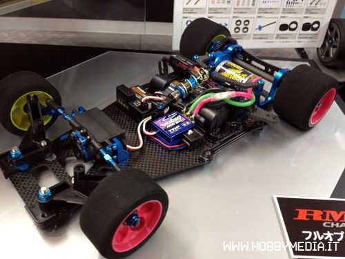
Tamiya 1/12 R/C RM-01 "Racing Master"


 11-07-2012, 06:45 AM
#707
In my experience
Kingpin centerline to wheel location plays an important role in how any car drives
By spacing the wheel away from the kingpin the handling on my RM became erratic, and gained too much front grip, with little control. I believe the inside step on the inch axle spaces the wheel out to the max width, any more and handling deteriorates rapidly
A wider front end on the RM would likely improve handling, corner speed, and stability
It's no accident that the carbon chassis has holes for the Associated front end, or possibly some other form of new front suspension ....
Last edited by RedBullFiXX; 11-07-2012 at 06:56 AM.
11-07-2012, 11:51 AM
#708
I thought about doing some measurements to see if the CRC or Associated front end would fit the bolt pattern on the RM01, but I kind of want to wait and see if Tamiya has something on the horizon for this car. Besides, I'm having good luck with the basic front end as it is.
11-07-2012, 12:58 PM
#709
I thought about doing some measurements to see if the CRC or Associated front end would fit the bolt pattern on the RM01, but I kind of want to wait and see if Tamiya has something on the horizon for this car. Besides, I'm having good luck with the basic front end as it is.
SpeedMerchant Old School, and R5 w/hyperdrive mounts are options I have been thinking about, but then it would no longer be a full Tamiya chassis....
11-07-2012, 02:08 PM
#710
Tech Fanatic
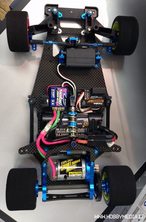
I don't have any 48 pitch spurs or pinions so i modified the smallest tamiya spur 90T by reaming the center hole to 10mm and then pushed in a 6x10mm ball bearing and some shims on both sides of the spur so the ball bearing can't come out of the spur. This brings me closer to the FDR you guys are using with a 17.5T motor,1 cell lipo and boosted.
Maximum FDR in this configuration is 1.94 (90 spur with 47 pinion), that's the biggest pinion/smallest spur combination that can be used.
So far i don't know anything about roll out things (still to find out/learn ) but i gues it will show itselfs on the track if a bigger pinion is needed or not.
Tomorrow will be the first time i try the car with a 17.5T motor&1 cell lipo, track is a medium sized one
Maximum FDR in this configuration is 1.94 (90 spur with 47 pinion), that's the biggest pinion/smallest spur combination that can be used.
So far i don't know anything about roll out things (still to find out/learn
) but i gues it will show itselfs on the track if a bigger pinion is needed or not.Tomorrow will be the first time i try the car with a 17.5T motor&1 cell lipo, track is a medium sized one
11-08-2012, 01:50 AM
#711
There are folks out there smarter than I to explain this in detail
In my experience
Kingpin centerline to wheel location plays an important role in how any car drives
By spacing the wheel away from the kingpin the handling on my RM became erratic, and gained too much front grip, with little control. I believe the inside step on the inch axle spaces the wheel out to the max width, any more and handling deteriorates rapidly
A wider front end on the RM would likely improve handling, corner speed, and stability
It's no accident that the carbon chassis has holes for the Associated front end, or possibly some other form of new front suspension ....
With the spacing we started with I ran 3 washers inside the wheels (CRCs on flanged bearings). The turning circle was very large to begin with (to give 172 mm) and the car wanted to carve more than I'd usually like. I took 2 of the washers out and that certainly made the car more direct, I was much happier with it.
I thought it could be more direct still though, and was contemplating getting another chassis made to narrow the front end by 2 mm.
That was after the first run. Now after a 2nd meeting I'm not so sure. It wasn't so far off. I put the car on pole actually, so overall I was fairly happy.
11-08-2012, 03:26 PM
#712
Tech Fanatic
Well tonight i did test the car with a 17.5T motor along with a 1cell lipo and boosted and man this car drives awesome.
The car felt great, wel balanced and not to agressive in steering.
The car went just the way i wanted to be, easy to control and so far i've only been using the kit tires.
I'm really looking forward to use the car with another up to date body and some Jaco tires.
All i can say is that i'm really impressed
11-08-2012, 07:04 PM
#713
Well tonight i did test the car with a 17.5T motor along with a 1cell lipo and boosted and man this car drives awesome.
The car felt great, wel balanced and not to agressive in steering.
The car went just the way i wanted to be, easy to control and so far i've only been using the kit tires.
I'm really looking forward to use the car with another up to date body and some Jaco tires.
All i can say is that i'm really impressed
The car felt great, wel balanced and not to agressive in steering.
The car went just the way i wanted to be, easy to control and so far i've only been using the kit tires.
I'm really looking forward to use the car with another up to date body and some Jaco tires.
All i can say is that i'm really impressed
11-09-2012, 04:21 AM
#715
Tech Fanatic
Today i got my jaco tires and body, but to mount the rear tires i had to modify the center hole. I did this with a body reamer.
The center hole wasn't big enough to go over the bearing on the right side and over the center ring on the left side. Is this a normal thing to do?
Another thing is that my servo is not a futaba (as mentioned before, my mistake) but a savox low profile, but so far i'm still unable to mount the servo saver correctly above the center line of the chassis.
The servo is mounted 1,2 mm out of center, it needs to move to the right side of the chassis.
Will the servo mounts of the TB-03 be the solution to clear out this problem?
Last edited by addicted2blue; 11-09-2012 at 04:31 AM.
11-10-2012, 12:27 PM
#716
Tech Fanatic
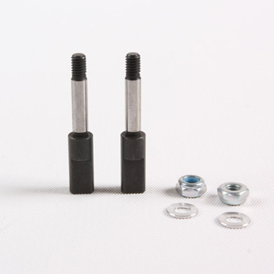
I just noticed from a picture that tamiya is going to release a carbon rear shaft and some spacers for the front end, just look at the picture below.