


 42Likes
Touring Car Project
 11-19-2019, 04:01 AM
#1
Hi,
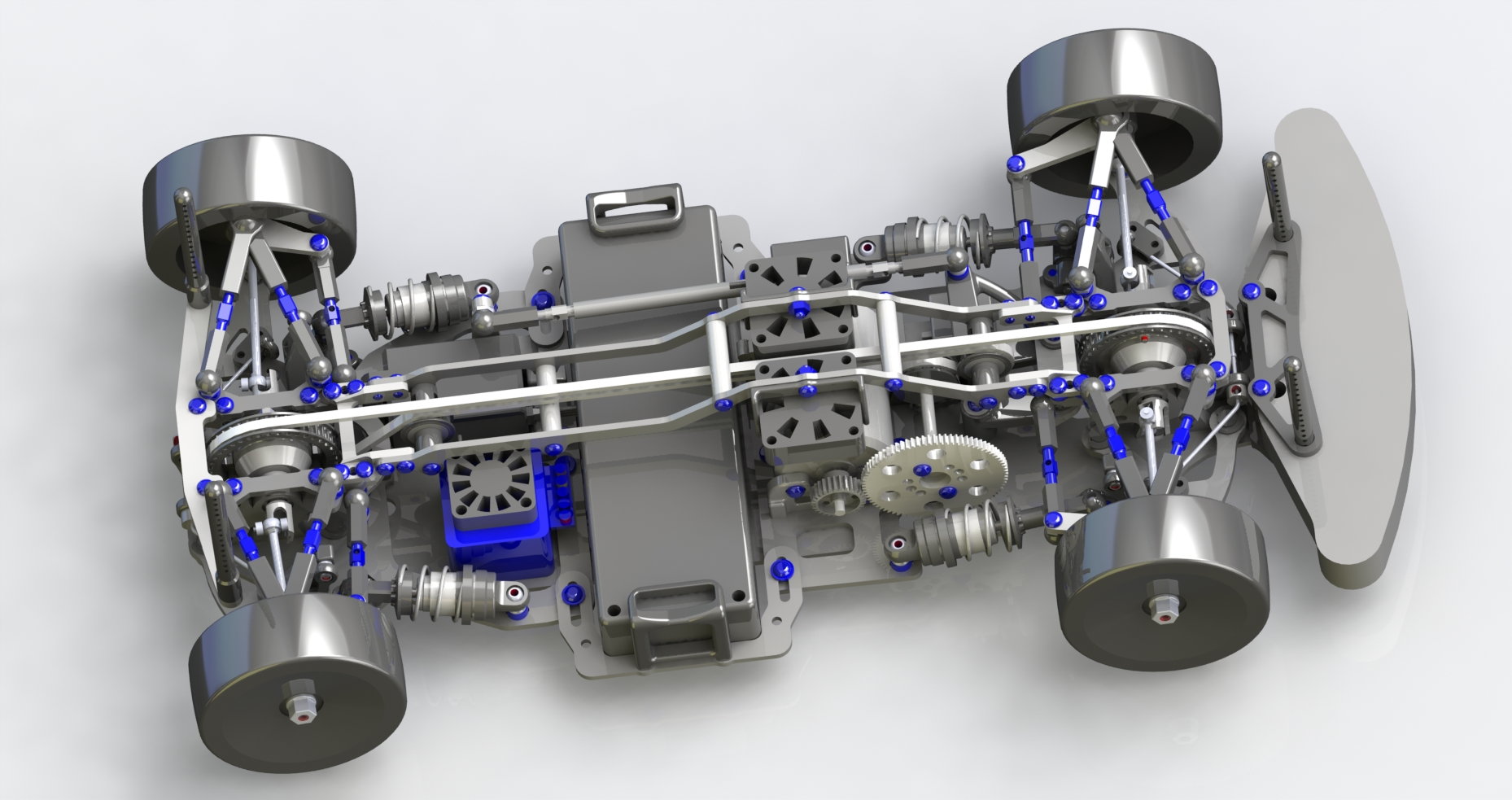
this is to introduce my latest development. Years ago I started with a Gizmo GZ1 and I still like the idea of a middle motor. The car shown in the picture uses quite some parts from Awesomatix (diff, spool, shafts,...), shocks from Xray a belt from Tamiya and also few parts from Serpent. Main characteristics are
- middle motor
- middle battery (movable to balance the car)
- middle belt
- laid down shocks
The prototype is ready to race on the workbench (but unfortunately I do not have much time to run it, especially not in winter...)
Let me know your thoughts, questions, ideas for improvement,...
Regard,
Andy
 11-19-2019, 06:08 AM
#3
Tech Master
iTrader: (15)
I dont understand how the shocks function
Also, shorty packs have such better capacity these days and a sideways full length pack is too wide and the chassis will scrape in corners. I think a shorty pack would really tighten this up to the "common" narrow chassis we see today.
Also, shorty packs have such better capacity these days and a sideways full length pack is too wide and the chassis will scrape in corners. I think a shorty pack would really tighten this up to the "common" narrow chassis we see today.
11-19-2019, 06:43 AM
#5

The spur gear just seems to be hanging out in space unsupported which is problematic; is the car to be a single belt (I only see one belt), and no clue how the shocks work in their current position. Tamiya used the IFS suspension on several cars, but the added belcranks and hardware to actuate the shocks gave poor performance. Interesting just the same.
11-19-2019, 06:51 AM
#6
To centralize the battery and motor, I'd go to a 3 belt nitro touring car setup.
Pushrod suspension is going to be a nightmare. Good luck.
Pushrod suspension is going to be a nightmare. Good luck.
11-19-2019, 07:06 AM
#7
Looks like a pretty cool design. Only thing I could see that might be a problem other than what others have stated is that the belt looks very close to rubbing on itself traveling fore and aft. But good job, I love seeing folks thinking outside the box.
11-19-2019, 07:28 AM
#8
Chassis width is gonna be a problem. That's addressable though. The belt path looks like it's going to need some guide bearings... and the more of those you have the more drag you have.
Three belt has a cost. For 25.5 and 21.5 racing, the car will be slower.
Pushrod has been done. TA06, FF03. It works fine.
Pushrod has been done. TA06, FF03. It works fine.
11-19-2019, 07:28 AM
#9
I'm startled that nobody has tried bolting arms to the chassis made out of spring steel, or spring carbon or fiberglass. Then just use a simple damper tube at each corner. Carpet onroad is pretty smooth after all.
11-19-2019, 07:33 AM
#10
Damper tubes are not consistent, and "more or less" suck. Especially for bits that move fast. But you're not "wrong" But there are things one could do to make damper tubes work "better". However.. you start quickly approaching a real shock.
11-19-2019, 07:48 AM
#11
The carbon fibre isn't used as a spring, but as a living hinge. (atleast that is my understanding)
Otherwise this car looks sweeeeeeeeeeeeeeeeeet!
11-19-2019, 08:10 AM
#12
Nice looking design . What cad package are you using , Solidworks perhaps ? Very cool serpentine
belt concept utilizing only 1-belt . From the rendering , is the drive pulley contacting the flat outside of the belt ?
I have a similar mid motor design just completed a month ago. In brief testing the true mid-motor placement
reduces torque steer to almost nothing. ALL the new designs from the major mfr's "mid motor madness "
still suffer from torque steer . Having the motor on one side & a big battery on the other, creates all
sorts of dynamic imbalance outside of the central roll axis . Good to see someone else actually designing & creating
something unique, rather than pulling commercial stuff off the shelf . Great job !!!!!
11-19-2019, 11:46 AM
#13
Tech Master
i apologize in advance. its a cool design that make me want to run my mouth off.
you can build a pack that would be vertical rather than horizontal.
you could move the shocks closer to the centerline with your arrangement fairly easy.
with your lever mechanism you could use an eccentric (cam) to adjust progression like a leaf spring does.
you could probably turn the steering arms around and put the servo on the bumper side of the front bulkhead.
the a700 dif would allow direct drive and run a belt from the front to the rear.
this would mean you would have to reorient the motor down the centerline of the chassis.
this is a cool design. its inspirational. dont take my comments to take away from what it is. I like it and im not saying my thoughts are better. they are just thoughts that came from looking at it.
11-19-2019, 12:08 PM
#14
Thanks everybody for sharing ideas. I will try to answer the questions and comment on some of the ideas.
Regarding the shocks please take a look at the following picture: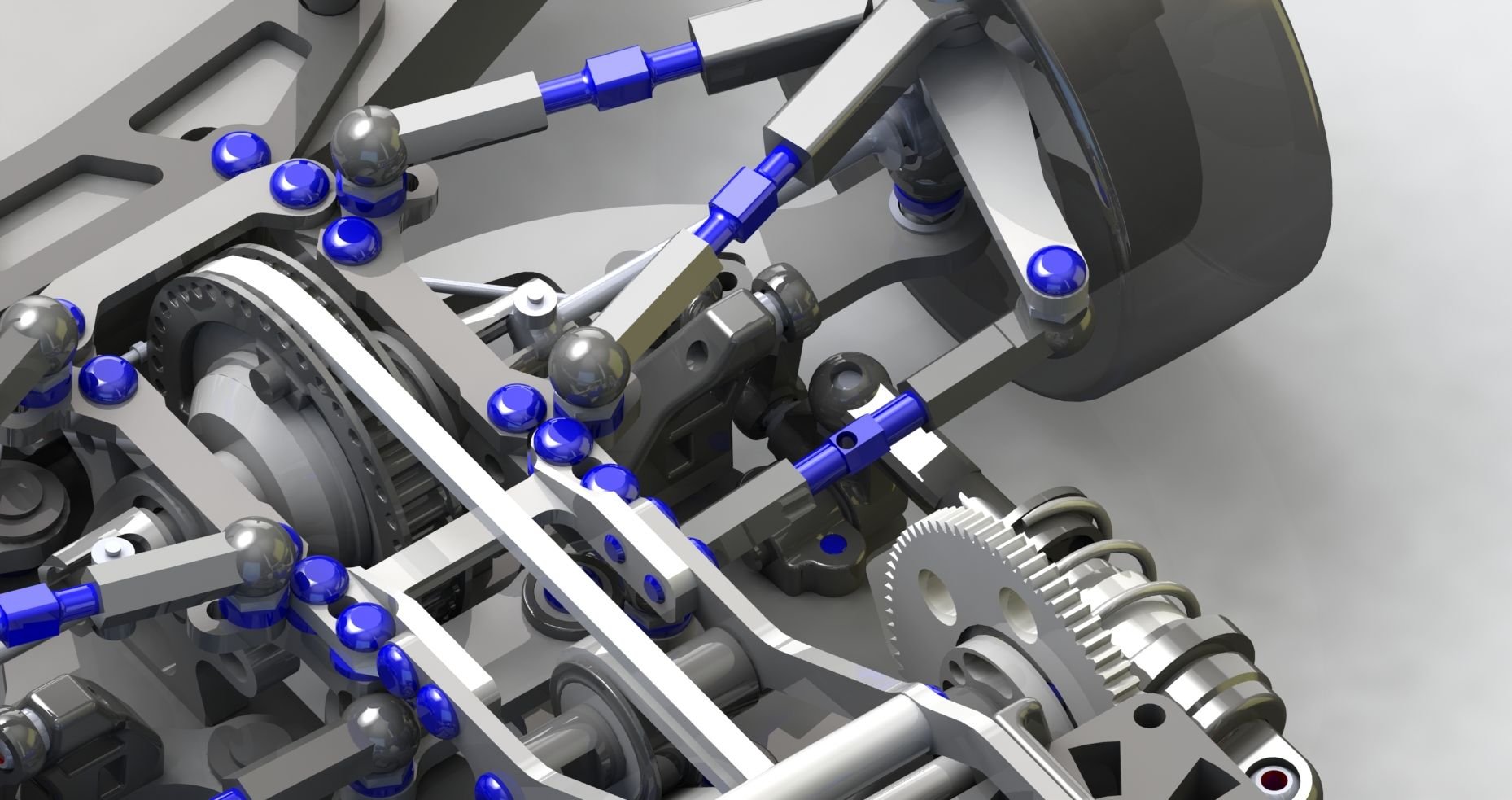
There is a little holder connected to the lower A-arms. This holder pulls at a lever that is able to rotate and thus move the piston of the shock.
What you also see in this picture: The spur gear has a second bearing right next to it. Actually the layshaft is one of the few �leftovers� from the GZ1.
Regarding shortys: I have designed a pair of battery holders that are short enough for shortys. Actually my prototype is built with a shorty right now:
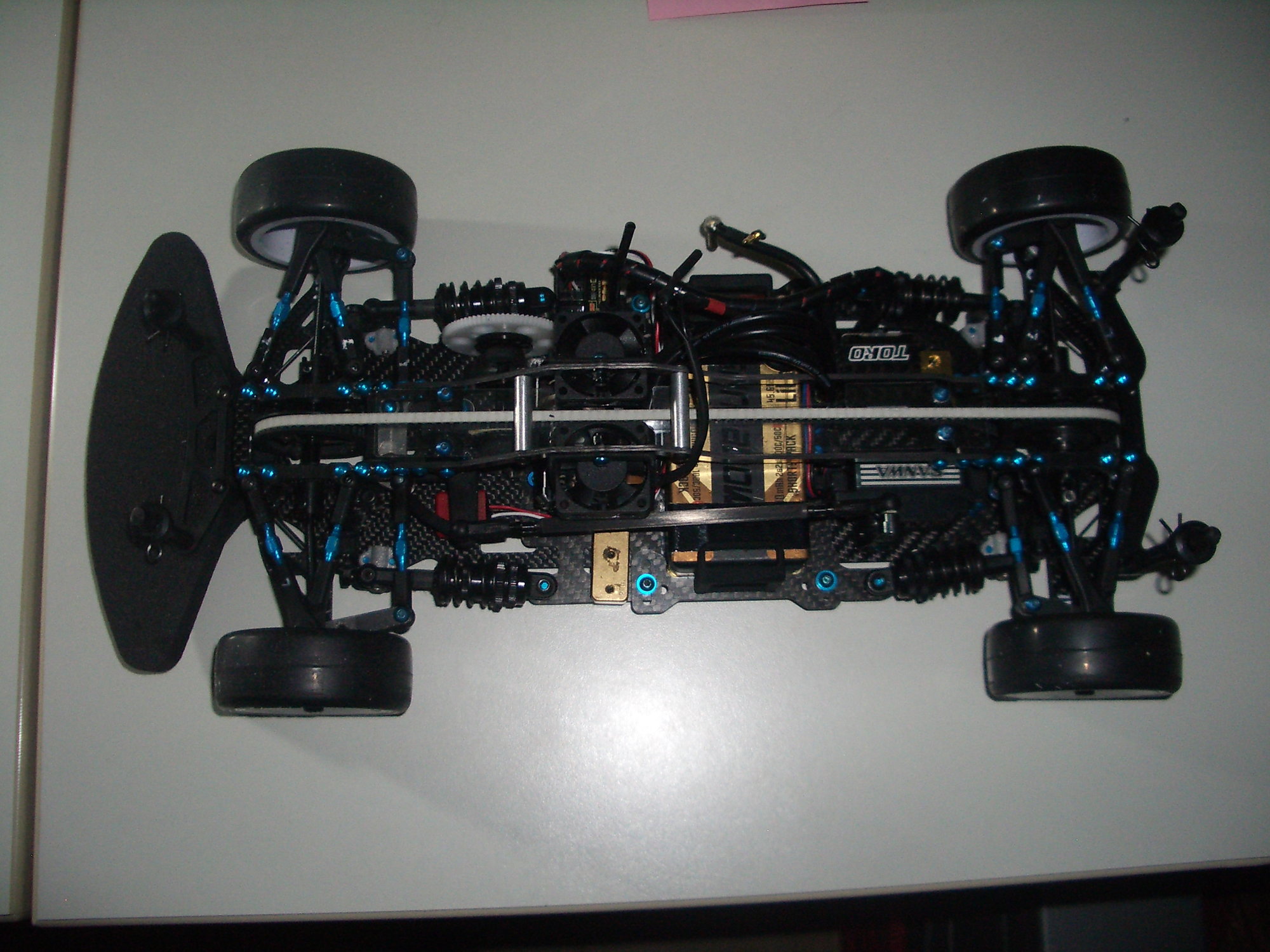
The battery holders allow for +-4mm of travel to adjust the balance of the car without having to add extra weight.
I also have thought about the belt having quite some wear if the teeth hit each other on a regular basis. For the moment I have separated them with a thin piece of lexan:
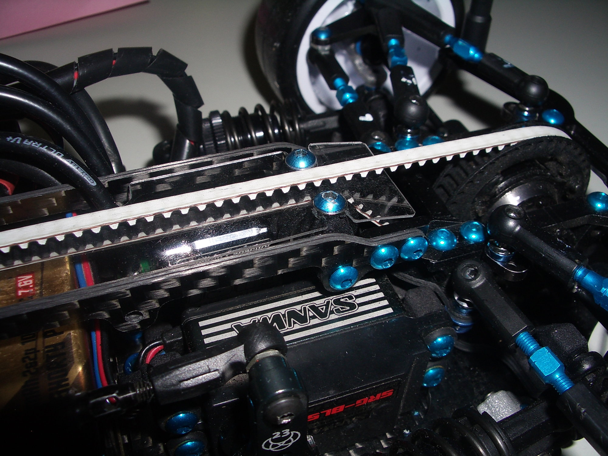
I might leave it away at some point to see if it really makes a difference. Also personally I do not like the idea of three belts in a touring car. I guess a concept with a belt so far on one side needs a very stiff chassis which nitro cars have but electric ones don�t.
CAD-system indeed is SWX.
Regarding the shocks please take a look at the following picture:
There is a little holder connected to the lower A-arms. This holder pulls at a lever that is able to rotate and thus move the piston of the shock.
What you also see in this picture: The spur gear has a second bearing right next to it. Actually the layshaft is one of the few �leftovers� from the GZ1.
Regarding shortys: I have designed a pair of battery holders that are short enough for shortys. Actually my prototype is built with a shorty right now:
The battery holders allow for +-4mm of travel to adjust the balance of the car without having to add extra weight.
I also have thought about the belt having quite some wear if the teeth hit each other on a regular basis. For the moment I have separated them with a thin piece of lexan:
I might leave it away at some point to see if it really makes a difference. Also personally I do not like the idea of three belts in a touring car. I guess a concept with a belt so far on one side needs a very stiff chassis which nitro cars have but electric ones don�t.
CAD-system indeed is SWX.
11-19-2019, 02:32 PM
#15
Chassis width is gonna be a problem. That's addressable though. The belt path looks like it's going to need some guide bearings... and the more of those you have the more drag you have.
Three belt has a cost. For 25.5 and 21.5 racing, the car will be slower.
Pushrod has been done. TA06, FF03. It works fine.
Three belt has a cost. For 25.5 and 21.5 racing, the car will be slower.
Pushrod has been done. TA06, FF03. It works fine.