


 245Likes
Rethinking 2wd Buggy Design
 11-22-2021, 05:47 AM
#376
doubling the mass of your spindle by adding a counterweight will probably cause more trouble for your x and y axis than solving whatever issue you're trying to fix on the z. you usually only see counterbalances on vertical mills and not on routers, likely for this reason. a simpler solution like a spring would probably be just as effective without causing any problems for your x and y.
also, there's some pretty good looking clearpath servo clones coming out of china nowadays that might be worth looking at.
also, there's some pretty good looking clearpath servo clones coming out of china nowadays that might be worth looking at.
 11-22-2021, 06:46 AM
#377
Tech Initiate
This is some great stuff! Interesting concept and incredible work with the custom chassis. What diff and belt you are planning to use?
11-22-2021, 02:30 PM
#378
doubling the mass of your spindle by adding a counterweight will probably cause more trouble for your x and y axis than solving whatever issue you're trying to fix on the z. you usually only see counterbalances on vertical mills and not on routers, likely for this reason. a simpler solution like a spring would probably be just as effective without causing any problems for your x and y.
also, there's some pretty good looking clearpath servo clones coming out of china nowadays that might be worth looking at.
also, there's some pretty good looking clearpath servo clones coming out of china nowadays that might be worth looking at.
I am no expert on any of this stuff, learning as I go.
Thanks for the suggestion.
11-22-2021, 02:37 PM
#379
Thanks. The diff is out of a TLR 22-4 2.0 because it is the narrowest diff I could find to work with the rear suspension design. As for belts, they will be custom ordered. I am thinking (after very little research) they will come from York Industries and I also want to look into Gates belts. Once I figure out the sizes/tooth count I might be able to find one from an rc manufacturer.
11-23-2021, 08:54 AM
#380
Tech Initiate
Thanks for the reply. Just googled it and it indeed looks super narrow!
Is there a reason why you havent extended the main chassis plate more towards the rear suspension lower arms? Is it because of the designed flex or? Cause i thought you could aid the airflow under the chassis by extending it more and maybe directing the flow towards the rear arms if they are a designed aerodynamic element of the car.
Or are the rear arms going to be wider, so you need space in there?
11-24-2021, 10:37 AM
#381
Thanks for the reply. Just googled it and it indeed looks super narrow!
Is there a reason why you havent extended the main chassis plate more towards the rear suspension lower arms? Is it because of the designed flex or? Cause i thought you could aid the airflow under the chassis by extending it more and maybe directing the flow towards the rear arms if they are a designed aerodynamic element of the car.
Or are the rear arms going to be wider, so you need space in there?
Is there a reason why you havent extended the main chassis plate more towards the rear suspension lower arms? Is it because of the designed flex or? Cause i thought you could aid the airflow under the chassis by extending it more and maybe directing the flow towards the rear arms if they are a designed aerodynamic element of the car.
Or are the rear arms going to be wider, so you need space in there?
I wanted to move the side pods as far forward as possible so the rear arms would see cleaner air at any suspension angle. I considered the idea of directing the air and even messed around with it in the air flow program but over time I came to the realization that I am dealing with slow air flow and air that is roughly 10 times thicker to scale. So I have have been looking at STOL (Short Take Off and Landing) aerodynamics for inspiration. And I have also learned that a lot of rc car aero is just a arodynamic wall that creates drag and through the cantiliver effect applies force to the wheels. So I plan to test rc aero somewhere between STOL aero and aerodynamic wall and see what that does.
But at this point I am heavy into building the tooling nessesary to make the car. That is why all you see is the CNC stuff on this thread at this time.
11-24-2021, 10:49 AM
#382
Tech Initiate
Okay, that makes sense. Thanks for the explanation!
11-25-2021, 09:41 PM
#383
Got started reworking the side pods and so far I am pleased. I will either be using brass threaded inserts or making custom aluminum ones that will have a light friction fit (to avoid deformations of the pod) and epoxy to hold in place. The second option is most likely. I also plan to make an aluminum nut that will go in the last bolt that holds the side pod covers at the rear suspension mount.
I also beefed up the front suspension mount at the back. This will be made from aluminum once the 4th axis on my new CNC is working


That's all for now.
I also beefed up the front suspension mount at the back. This will be made from aluminum once the 4th axis on my new CNC is working
That's all for now.
12-05-2021, 05:00 PM
#384
I've been working on getting my 3d Printer tuned in for making my printed parts for my new car. I have got everything really good for PLA and have made the side pods. I also learned that you can program in pauses in prints to insert objects. So I experimented with inserting brass threaded inserts, and the results are great. At some point I would like to make aluminum inserts but I have to do some mods to my lathe before that.
I also have been playing with more exotic filaments like Nylon Carbon Fiber but due to moisture in the filament the print results were poor. I am currently drying the filament and will try later. I may also contact 3DXTech and inquire about which filament they think might work best for this project.
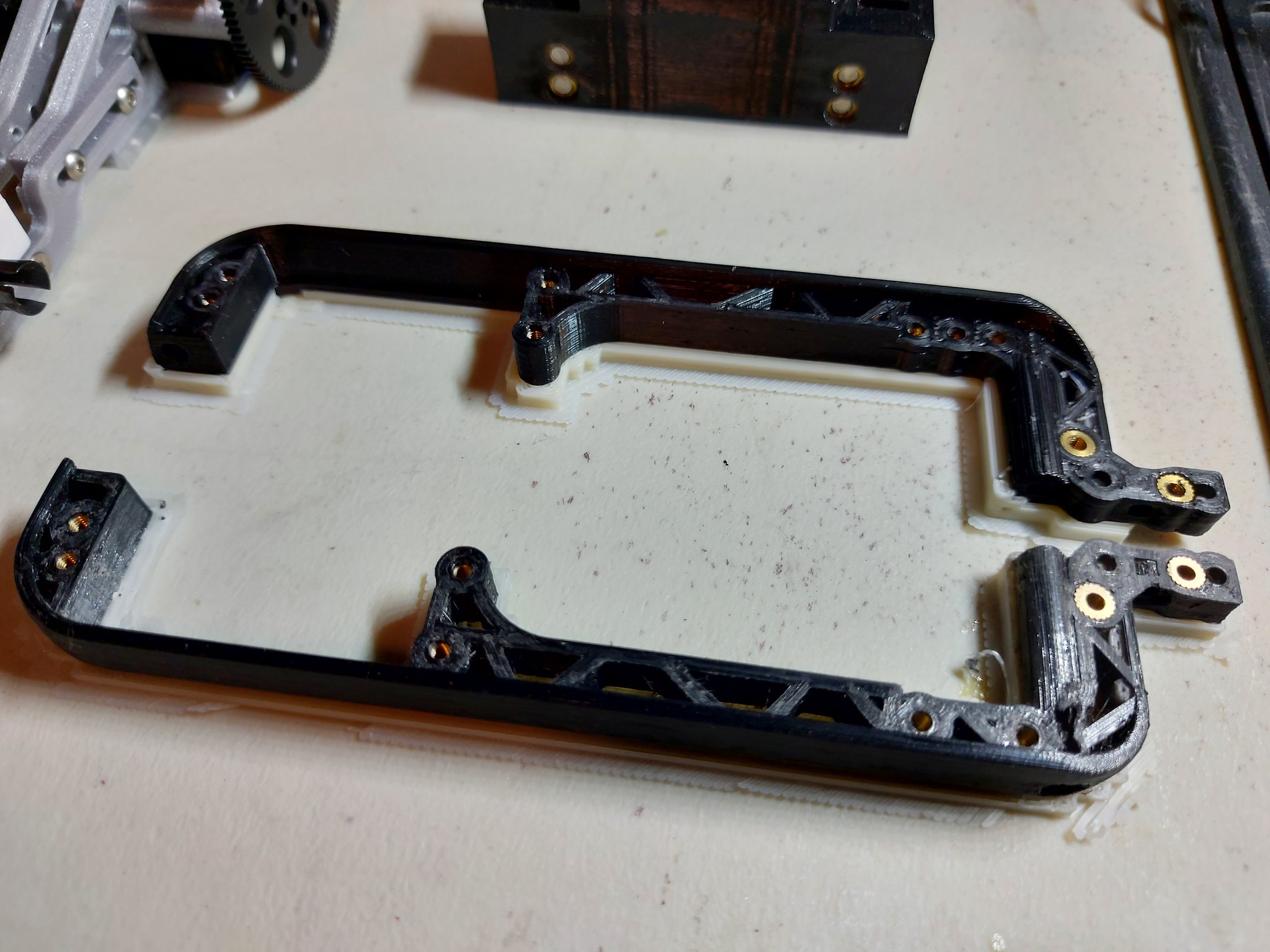
Here are two of my successful prints. the one on top is the best (its PLA). The one below is PETG, decent print but I think the cheap filament is hindering print quality. PETG print closeups below. I was also having an issue with layer adhesion, again better filament needed (I think). But you can see how well the brass insert worked!


Here is the PLA side pod (the other is printing as I write this) and you can see the difference in the print quality. But PLA is too temperature sensative to be a long term solution. On a hot day this would be very rubbery. In these pics the printer is paused to insert the threaded inserts.


It doesn't look like I got a lot done but there were a bunch of failed prints and testing to make good quality dimensionally accurate parts.
I also got the bolts for the spindle and got that mounted. Then I modified the counter weight modified and printed with threaded inserts.


I have since modified the peice that holds the pulleys and printed it but again I had further issues with layer adhesion. I have added temporary carboard walls to my printer enclosure and this seems to have helped but I have to do more testing.
This is the old counter weight mount, I haven't mounted the new one yet.

The end plates on the pulley mounts that you can see in the picture above will be made out of aluminum at some point.
This the new counter weight mount. It turned out great and should work really well.


Currently I am figuring out how the transmission will mount to the side pods. I have the side pod mounting points figured out but I am not sure exactly how it will interface with the transmission.
I also have been playing with more exotic filaments like Nylon Carbon Fiber but due to moisture in the filament the print results were poor. I am currently drying the filament and will try later. I may also contact 3DXTech and inquire about which filament they think might work best for this project.
Here are two of my successful prints. the one on top is the best (its PLA). The one below is PETG, decent print but I think the cheap filament is hindering print quality. PETG print closeups below. I was also having an issue with layer adhesion, again better filament needed (I think). But you can see how well the brass insert worked!
Here is the PLA side pod (the other is printing as I write this) and you can see the difference in the print quality. But PLA is too temperature sensative to be a long term solution. On a hot day this would be very rubbery. In these pics the printer is paused to insert the threaded inserts.
It doesn't look like I got a lot done but there were a bunch of failed prints and testing to make good quality dimensionally accurate parts.
I also got the bolts for the spindle and got that mounted. Then I modified the counter weight modified and printed with threaded inserts.
I have since modified the peice that holds the pulleys and printed it but again I had further issues with layer adhesion. I have added temporary carboard walls to my printer enclosure and this seems to have helped but I have to do more testing.
This is the old counter weight mount, I haven't mounted the new one yet.
The end plates on the pulley mounts that you can see in the picture above will be made out of aluminum at some point.
This the new counter weight mount. It turned out great and should work really well.
Currently I am figuring out how the transmission will mount to the side pods. I have the side pod mounting points figured out but I am not sure exactly how it will interface with the transmission.
Last edited by NitrousBIG; 12-05-2021 at 05:10 PM.
12-05-2021, 05:29 PM
#385
Tech Initiate
You should try this CF/PETG filament:
https://www.3djake.fi/formfutura/carbonfiltm-black
Much better option example for those side pods than nylon/nylon cf. Doesnt warp at all, sticks to powder coated bed like crazy, isnt as moisture sensitive as nylon and is very stiff material because of added carbon fiber. I've printed almost all my rc car parts from that filament, chassis, bearing hubs, transmission cases, upper decks, servo arms, shock towers etc. And those parts go directly to the real use.
CF needs a hardened nozzle though and nozzles outer surface will be messy after printing with that filament as for some reason that filament tends to do little bit uneven layer surface where the cf strings with petg are pointing different directions. When the nozzle sweeps over those, it will gather some of the filament. I think it adds little bit strength though, or then my print settings for that filament are wrong. I also print that with 275c nozzle and 80c bed with my i3MK3S.
I would avoid pausing prints to add those inserts. I dont know about others, but I've had bad experiences with pausing prints causing weaker layer adhesion between the paused layers. I usually just design the hole where the insert is going to 5,2-5,3mm and then use 5mm od inserts that i install with soldering iron to the parts.
12-05-2021, 05:39 PM
#386
You should try this filament:
https://www.3djake.fi/formfutura/carbonfiltm-black
Much better option example for those side pods than nylon/nylon cf. Doesnt warp at all, sticks to powder coated bed like crazy, isnt as moisture sensitive as nylon and is very stiff material because of added carbon fiber. I've printed almost all my rc car parts from that filament, chassis, bearing hubs, transmission cases, upper decks, servo arms etc. And those parts go directly to the real use.
CF needs a hardened nozzle though and nozzles outer surface will be messy after printing with that filament as for some reason that filament tends to do little bit uneven layer surface where the cf strings with petg are pointing different directions. When the nozzle sweeps over those, it will gather some of the filament. I think it adds little bit strength though, or then my print settings for that filament are wrong.
I would avoid pausing prints to add those inserts. At least I've had bad experiences with pausing prints causing weaker layer adhesion between the paused layers. I usually just design the hole where the insert is going to 5,2-5,3mm and then use 5mm od inserts that i install with soldering iron to the parts.
12-06-2021, 11:39 AM
#387
Tech Adept
Do you have plans that is it better for high grip or lov grip surface.
It feels like it would be better on high grip..
It feels like it would be better on high grip..
12-07-2021, 11:29 AM
#388
Last edited by NitrousBIG; 12-13-2021 at 07:00 PM.
01-01-2022, 05:38 PM
#389
It's alive!!!! The CNC is thrown together, the wiring is temporary (will be shielded), the table is made of wood (will be aluminum), there is no cooling (will have flood coolant), spindle couter weight system inclomplete, 3D printed parts (will be made or aluminum) and no enclosure (makes a big mess).
But dispite all that I am impressed at how well it is working. I still have a ton of work to do with the project but its gonna take time.
OK.... Like I said much of this is temporary! I want to start using some coolant to cool the cutter so I plan to use a spray bottle or maybe a misting system and need to collect the coolant. Soooo, I picked up a cookie sheet and attached it the the temporary wood table. Then I attached a block of UHMW plastic to the cookie sheet that I am making into a temprary fixture plate. Then I can start making the aluminum parts for the machine.

Here it is surfacing the UHMW block to make the temporary surface plate. I have threaded insert that I will put in it so I can bolt things to it.

UHMW is weird stuff. While cutting it produces a bure that ceeps growing as you cut. There are ways to eliminate this but I don't use the material enough.


After a light sanding it's all cleaned up. It is not perfect but good enough for now. The spindel is out of tram, working on making a tramming tool right now. I love the cookie sheet, it looks so ghetto!
This is my main focus at this point. I need to build an enclosure, water proof it and get the coolant system working. All the wiring will go straight up to the top where the electronics will be located.

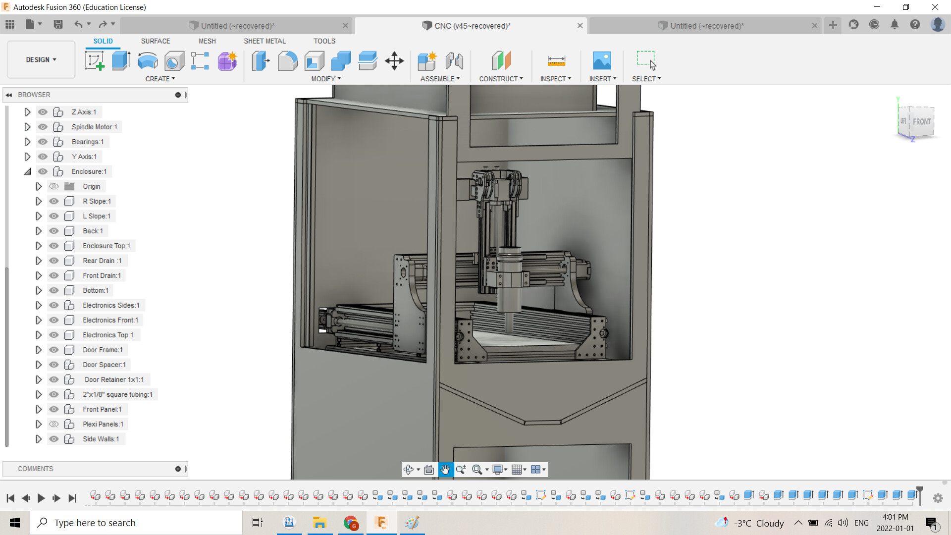
This is the electronics enclosure. You can also see the doors that will open vertically. My hobby room is a storage room so its tight. Swing out doors will get in the way. So these doors will open vertically and slide out the top to remove. And the whole enclosure will be on fixed castes so it can roll out to work on the CNC.

Below I will have a cabinet. I don't think it will have doors. It will contain my machinist tool box, coolant tank, filter tank and possibly a tool assorment for the CNC and hold down assortment.
If I can get the CAD done on the enclosure I am going to see if I can get the plywood cut to assemble the enclosure ASAP.
For now I am working on cleaning and reorganizing my hobby room so the enclosure can fit in the room. Then I can start making more parts for the new car.
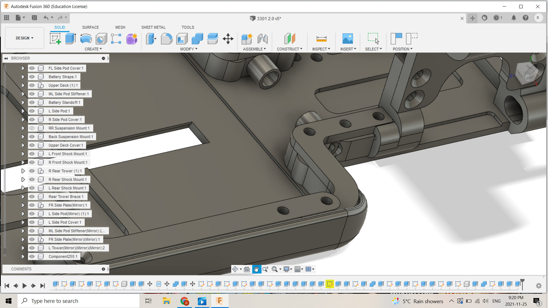
Update on the new car. I have been making the first part, the side pods, as seen in earlier posts. But I have the first part that will go on the car.

Here it is sitting on the temporary CNC fixture plate. I am pleased with the finish of this part so far. There are still a few threaded inserts I need to install.

This is the under side of the part. You can see the surface left from printing on the support structure.

Again the under side.

Here is where the transmission will attach the side pods. This is to reduce the impact of the transmission on chassis flex.
I have also been making changes to the design around the rear of the chassis to transfer the flex charactieristics thoughout the chassis. I did this by changing the radius at the rear of the chassis

The radius where the rear of the chassis meets the side pod area is dramatically increased.
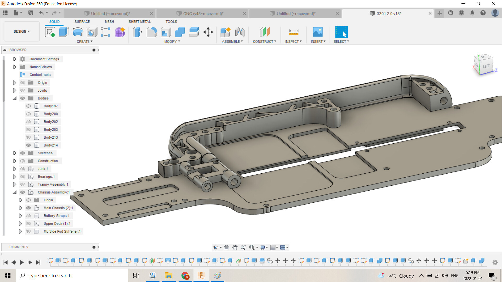
Here you can see the transmission mount and the side pod. I have some more work to do on the in chassis circuit board but you can see the hole in the center of the tranny mount where the steering servo wires coming form the reciever will attach to the chassis.
I'll update when I have more done. Till then!
But dispite all that I am impressed at how well it is working. I still have a ton of work to do with the project but its gonna take time.
OK.... Like I said much of this is temporary! I want to start using some coolant to cool the cutter so I plan to use a spray bottle or maybe a misting system and need to collect the coolant. Soooo, I picked up a cookie sheet and attached it the the temporary wood table. Then I attached a block of UHMW plastic to the cookie sheet that I am making into a temprary fixture plate. Then I can start making the aluminum parts for the machine.
Here it is surfacing the UHMW block to make the temporary surface plate. I have threaded insert that I will put in it so I can bolt things to it.
UHMW is weird stuff. While cutting it produces a bure that ceeps growing as you cut. There are ways to eliminate this but I don't use the material enough.
After a light sanding it's all cleaned up. It is not perfect but good enough for now. The spindel is out of tram, working on making a tramming tool right now. I love the cookie sheet, it looks so ghetto!
This is my main focus at this point. I need to build an enclosure, water proof it and get the coolant system working. All the wiring will go straight up to the top where the electronics will be located.
This is the electronics enclosure. You can also see the doors that will open vertically. My hobby room is a storage room so its tight. Swing out doors will get in the way. So these doors will open vertically and slide out the top to remove. And the whole enclosure will be on fixed castes so it can roll out to work on the CNC.
Below I will have a cabinet. I don't think it will have doors. It will contain my machinist tool box, coolant tank, filter tank and possibly a tool assorment for the CNC and hold down assortment.
If I can get the CAD done on the enclosure I am going to see if I can get the plywood cut to assemble the enclosure ASAP.
For now I am working on cleaning and reorganizing my hobby room so the enclosure can fit in the room. Then I can start making more parts for the new car.
Update on the new car. I have been making the first part, the side pods, as seen in earlier posts. But I have the first part that will go on the car.
Here it is sitting on the temporary CNC fixture plate. I am pleased with the finish of this part so far. There are still a few threaded inserts I need to install.
This is the under side of the part. You can see the surface left from printing on the support structure.
Again the under side.
Here is where the transmission will attach the side pods. This is to reduce the impact of the transmission on chassis flex.
I have also been making changes to the design around the rear of the chassis to transfer the flex charactieristics thoughout the chassis. I did this by changing the radius at the rear of the chassis
The radius where the rear of the chassis meets the side pod area is dramatically increased.
Here you can see the transmission mount and the side pod. I have some more work to do on the in chassis circuit board but you can see the hole in the center of the tranny mount where the steering servo wires coming form the reciever will attach to the chassis.
I'll update when I have more done. Till then!
01-30-2022, 07:40 PM
#390
There isn't much change visually but my brain has been going a million miles an hour getting things figured out with the CNC, the car and 3d printing.
The CNC:
I have some 3 flute small diameter endmills that cut beautifully but plug up when cutting aluminum. There isn't enough room in the flutes to evacuate the chips and the cutter is getting hot due to no cooling.This combination plugged the endmill but I managed to stop it before it broke. FYI use Lye in water to disolve the aluminum, this was amazing! Once I have the cooling in place I am going to try the 3 flute cutters again.
After doing a bunch of research I am going to order a few Datron Single flutes for aluminum and plastic. I should be able to cut with light coolant.
Next after looking into fixturing I am going to order an Saunders Machine Fixture Plate, vises and various jaws. BUT, with the border closed I am going to wait until its open to save myself hundreds in shipping. In the mean time I am thinking over a few options.

I am thinking about using this plate as a temporary surface. The Saunders plate I want is an inch thick and far less flex.
I also still have to do some testing to varify the dimensional accuracy, tram in the cutting head and then cut the aluminum parts to replace the 3d printed ones.
3D Printer and the Car Parts:
I have been playing with the 3D Printer Slicer getting the quality to where I want it and dealing with the issues of the Multi Material Unit (MMU). The MMU is working quite well after messing with it a bunch but I am still having issues with the fillament jamming in the hot end. 3DX Tech is sending me a sample of their X1 disolvable filament and I am hoping this will solve some of my issues.
The other thing I have been messing with is the redesign of the tranny, side pods and chassis. And I think it's coming together. So far I really like the design and after finishing a little work on the chassis in cad I am going to re-print the chassis so I can see the full assembly before cutting the aluminum. I am also still strugling with how I am going to bend the kick up in the front. Over the next few weeks I am going to rebuild the sheet metal brake at work and do some testing. Hopefully this will work on 3.1ish mm aluminum?!?!?!?
Anyways this is what I have thus far:

Here is the latest re-design of the rear tranny. The quality of the print on the diff cover is sub par. I tried reprinting today but with poor results. I need to change the orientation while printing and use a disolvable filament as support. I am currently using PLA as support with the PETG Carbon Fiber for the part. But this has to be broken away and takes a long time to do. So I have high hopes for the 3DX Tech fillament.

Here you can see the tranny mount the attaches the tranny to the side pods suspending it over the chassis

Yesterday I printed the side pods in PETG CF, agian, and finally an acceptable final result.
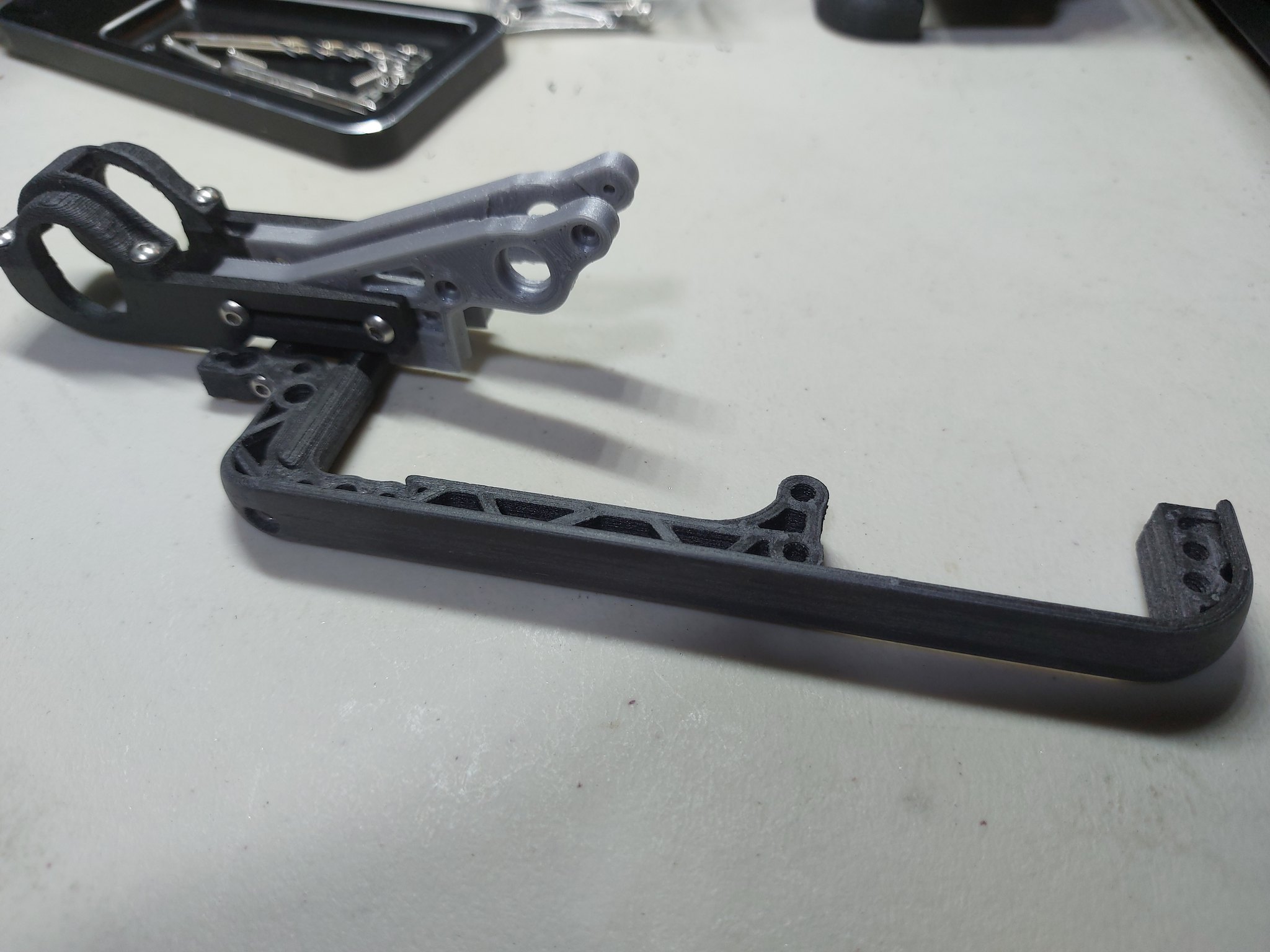
Today, after some post processing (filing and sanding), I got the side pods attached to the tranny. The side pods are the first real parts that are the final product. The car will be built around these parts.
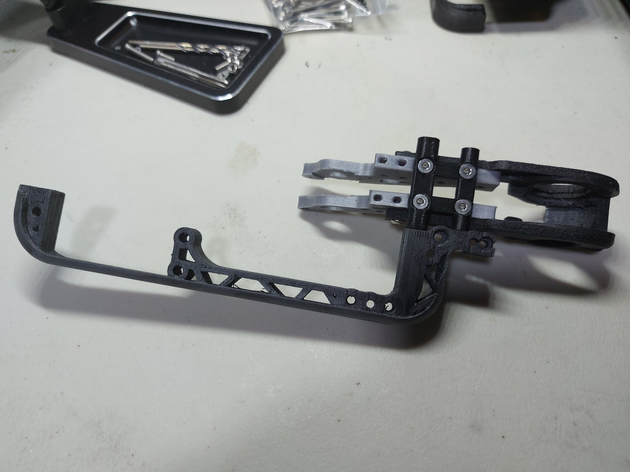

You can see that I no longer have the brass thread inserts. I have decided to make them out of aluminum so the will be like stand offs to the Carbon Fiber side pod covers (upper deck). But I need to do a little work to my lathe before making these.

The major change to the side pod design is the long screws in the side pods to secure the tranny.
So that is where I am at. I think my focus is going to shift to the CNC Enclosure design so I can cut the pieces on the CNC at work in the wood shop. I also have to build a tramming bar so I can tram my spindle and I might mess around with checking the dimensional accuracy of the machine. Also I have to finish updating the chassis and reprint.
Until then!
The CNC:
I have some 3 flute small diameter endmills that cut beautifully but plug up when cutting aluminum. There isn't enough room in the flutes to evacuate the chips and the cutter is getting hot due to no cooling.This combination plugged the endmill but I managed to stop it before it broke. FYI use Lye in water to disolve the aluminum, this was amazing! Once I have the cooling in place I am going to try the 3 flute cutters again.
After doing a bunch of research I am going to order a few Datron Single flutes for aluminum and plastic. I should be able to cut with light coolant.
Next after looking into fixturing I am going to order an Saunders Machine Fixture Plate, vises and various jaws. BUT, with the border closed I am going to wait until its open to save myself hundreds in shipping. In the mean time I am thinking over a few options.
I am thinking about using this plate as a temporary surface. The Saunders plate I want is an inch thick and far less flex.
I also still have to do some testing to varify the dimensional accuracy, tram in the cutting head and then cut the aluminum parts to replace the 3d printed ones.
3D Printer and the Car Parts:
I have been playing with the 3D Printer Slicer getting the quality to where I want it and dealing with the issues of the Multi Material Unit (MMU). The MMU is working quite well after messing with it a bunch but I am still having issues with the fillament jamming in the hot end. 3DX Tech is sending me a sample of their X1 disolvable filament and I am hoping this will solve some of my issues.
The other thing I have been messing with is the redesign of the tranny, side pods and chassis. And I think it's coming together. So far I really like the design and after finishing a little work on the chassis in cad I am going to re-print the chassis so I can see the full assembly before cutting the aluminum. I am also still strugling with how I am going to bend the kick up in the front. Over the next few weeks I am going to rebuild the sheet metal brake at work and do some testing. Hopefully this will work on 3.1ish mm aluminum?!?!?!?
Anyways this is what I have thus far:
Here is the latest re-design of the rear tranny. The quality of the print on the diff cover is sub par. I tried reprinting today but with poor results. I need to change the orientation while printing and use a disolvable filament as support. I am currently using PLA as support with the PETG Carbon Fiber for the part. But this has to be broken away and takes a long time to do. So I have high hopes for the 3DX Tech fillament.
Here you can see the tranny mount the attaches the tranny to the side pods suspending it over the chassis
Yesterday I printed the side pods in PETG CF, agian, and finally an acceptable final result.
Today, after some post processing (filing and sanding), I got the side pods attached to the tranny. The side pods are the first real parts that are the final product. The car will be built around these parts.
You can see that I no longer have the brass thread inserts. I have decided to make them out of aluminum so the will be like stand offs to the Carbon Fiber side pod covers (upper deck). But I need to do a little work to my lathe before making these.
The major change to the side pod design is the long screws in the side pods to secure the tranny.
So that is where I am at. I think my focus is going to shift to the CNC Enclosure design so I can cut the pieces on the CNC at work in the wood shop. I also have to build a tramming bar so I can tram my spindle and I might mess around with checking the dimensional accuracy of the machine. Also I have to finish updating the chassis and reprint.
Until then!