


 133Likes
F1 prototype 2017
 06-22-2017, 09:55 AM
#61
I've been silently watching this thread for a while and I have to speak up and say you should be incredibly proud of your design G-rem. Absolutely awesome to design your own car. It is a marvel of engineering.
If you ever make the shift to sell the printed parts you designed along with a Bill of Material for purchased parts needed (along with modifications detailed), I will definitely be standing in line waiting for my chance to send cash your way.
Major props to you
If you ever make the shift to sell the printed parts you designed along with a Bill of Material for purchased parts needed (along with modifications detailed), I will definitely be standing in line waiting for my chance to send cash your way.
Major props to you
 06-22-2017, 01:06 PM
#62

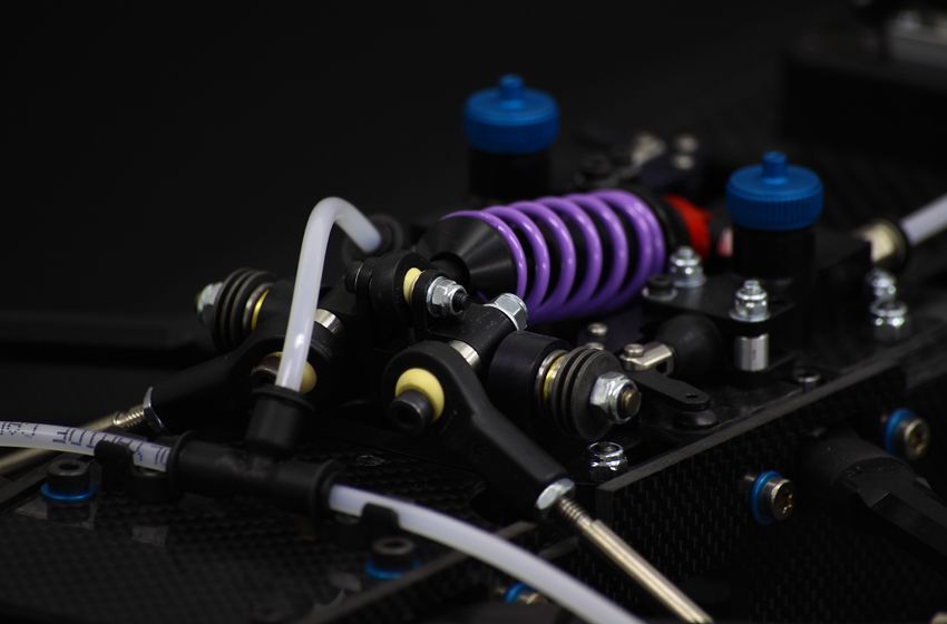
Some improvement of the front monoshock system:

I added 2 small PN mini-z front springs in order to have some influence on lateral moves when cornering, so that under-load side can move up sligthly (around 3mm travel) while the other side can move down.
It also act as a sway bar, and I can fine-tune the effect by switching to other rate springs.
G-rem
Damping?
06-23-2017, 01:18 AM
#64
Tech Initiate
Overall your design seems very well thought out. Your design is something I wanted to see for a long time. Very well done!
I love the front mono-shock design. I though its quite an innovation. It avoids the need for a front stabiliser bar and the associated linkage. I am not sure about the use of springs for roll movement, as I'm uncertain if the springs will provide adequate stiffness in roll. As long as there is a few mm of space on each side, it can be packed with spacers, washers and possibly several O-rings per side. I doubt there will be much need for a front roll-damper unit. The O-rings together with the tire's internal damping should provide adequate damping in roll. Due to the very attractive IRS setup, your chassis design will have unusually good damping in roll from the rear end of the car.
My critical comment is about the front to rear CG balance. I'd be inclined to go for a lateral mounted battery to allow the COG to be moved as far rearward as possible. I would like to get the motor closer the rear axle if it can be done.
Thanks for showing your design and all the great pics.
06-23-2017, 02:00 AM
#65
Overall your design seems very well thought out. Your design is something I wanted to see for a long time. Very well done!
I love the front mono-shock design. I though its quite an innovation. It avoids the need for a front stabiliser bar and the associated linkage. I am not sure about the use of springs for roll movement, as I'm uncertain if the springs will provide adequate stiffness in roll. As long as there is a few mm of space on each side, it can be packed with spacers, washers and possibly several O-rings per side. I doubt there will be much need for a front roll-damper unit. The O-rings together with the tire's internal damping should provide adequate damping in roll. Due to the very attractive IRS setup, your chassis design will have unusually good damping in roll from the rear end of the car.
I love the front mono-shock design. I though its quite an innovation. It avoids the need for a front stabiliser bar and the associated linkage. I am not sure about the use of springs for roll movement, as I'm uncertain if the springs will provide adequate stiffness in roll. As long as there is a few mm of space on each side, it can be packed with spacers, washers and possibly several O-rings per side. I doubt there will be much need for a front roll-damper unit. The O-rings together with the tire's internal damping should provide adequate damping in roll. Due to the very attractive IRS setup, your chassis design will have unusually good damping in roll from the rear end of the car.
I did some static testings with o-rings instead of springs, and it works but not as good as I hoped (mainly because I hardly have the space to put only one o-ring). With the little update I made yesterday, I'll be able to test either springs, either several o-ring or even spacers. I'm really looking forward to track testing in order to validate the best option (and I really, really want to make this monoshock design working as I find it very cool looking; but if it ever fails, I can switch to classic IFS with 2 shocks, that I know it will work properly as it was the setup I used last year on my 3R FGX prototype)
My critical comment is about the front to rear CG balance. I'd be inclined to go for a lateral mounted battery to allow the COG to be moved as far rearward as possible. I would like to get the motor closer the rear axle if it can be done.
Thanks for showing your design and all the great pics.
Thanks for showing your design and all the great pics.
Unfortunately, the motor is already at the most rearward position as I could put it, everything is super tight regarding transmission and rear suspension...
Regards,
G-rem
06-23-2017, 05:29 PM
#66
Tech Initiate
Hi G-Rem,
I thought about another alternative to the springs or rubber O-ring roll-compliance device. Instead of allowing the lateral movement of the damper bellcrank, maybe the pivot block could be mounted on a separate FRP mounting plate that allows controlled lateral compliance. There are probably more examples of this idea in old pan car chassis using T-plates. It may move either by torsion or rotation about a vertical pivot axis. Perhaps with one bearing and some rubber grommets so the lateral movement of the mounting plate can be controlled. Maybe it would be more clear if I provided sketch of my concept. It needs some more thought and design work so it will provide reasonable centering, to ensure the car's handling will be the same in both left and right hand corners.
I thought about another alternative to the springs or rubber O-ring roll-compliance device. Instead of allowing the lateral movement of the damper bellcrank, maybe the pivot block could be mounted on a separate FRP mounting plate that allows controlled lateral compliance. There are probably more examples of this idea in old pan car chassis using T-plates. It may move either by torsion or rotation about a vertical pivot axis. Perhaps with one bearing and some rubber grommets so the lateral movement of the mounting plate can be controlled. Maybe it would be more clear if I provided sketch of my concept. It needs some more thought and design work so it will provide reasonable centering, to ensure the car's handling will be the same in both left and right hand corners.
06-23-2017, 10:51 PM
#68

Hi G-Rem,
I thought about another alternative to the springs or rubber O-ring roll-compliance device. Instead of allowing the lateral movement of the damper bellcrank, maybe the pivot block could be mounted on a separate FRP mounting plate that allows controlled lateral compliance. There are probably more examples of this idea in old pan car chassis using T-plates. It may move either by torsion or rotation about a vertical pivot axis. Perhaps with one bearing and some rubber grommets so the lateral movement of the mounting plate can be controlled. Maybe it would be more clear if I provided sketch of my concept. It needs some more thought and design work so it will provide reasonable centering, to ensure the car's handling will be the same in both left and right hand corners.
I thought about another alternative to the springs or rubber O-ring roll-compliance device. Instead of allowing the lateral movement of the damper bellcrank, maybe the pivot block could be mounted on a separate FRP mounting plate that allows controlled lateral compliance. There are probably more examples of this idea in old pan car chassis using T-plates. It may move either by torsion or rotation about a vertical pivot axis. Perhaps with one bearing and some rubber grommets so the lateral movement of the mounting plate can be controlled. Maybe it would be more clear if I provided sketch of my concept. It needs some more thought and design work so it will provide reasonable centering, to ensure the car's handling will be the same in both left and right hand corners.
09-21-2017, 12:49 AM
#69
Tech Initiate
How's the progress coming on the chassis?
I remembered that I had seen a chassis similar to yours somewhere before that had the mono-shock layout but it had escaped me this entire time but I finally came across it again.
It's called the RS5 F1 and it's a 1/5 scale beauty. Is this the chassis where you got the idea of the mono-shock mounting mechanism? While, in this picture they have what seems to be a boot/damper on the outside to absorb the lateral forces, why wouldn't you want to have a rocker for each side?
09-21-2017, 06:28 AM
#70
How's the progress coming on the chassis?
I remembered that I had seen a chassis similar to yours somewhere before that had the mono-shock layout but it had escaped me this entire time but I finally came across it again.
It's called the RS5 F1 and it's a 1/5 scale beauty. Is this the chassis where you got the idea of the mono-shock mounting mechanism? While, in this picture they have what seems to be a boot/damper on the outside to absorb the lateral forces, why wouldn't you want to have a rocker for each side?
I remembered that I had seen a chassis similar to yours somewhere before that had the mono-shock layout but it had escaped me this entire time but I finally came across it again.
It's called the RS5 F1 and it's a 1/5 scale beauty. Is this the chassis where you got the idea of the mono-shock mounting mechanism? While, in this picture they have what seems to be a boot/damper on the outside to absorb the lateral forces, why wouldn't you want to have a rocker for each side?
I am currently hard working on the V3 prototype, my goal is to get it printed by the end of this month, but dealing with small adjustments mainly is more time consuming than designing a raw part from scratch

I've refined the front suspension system, the steering system, the floor plates, the rear diffusor; worked on the rear bulkheads to lower the diff so that I will be able to lower the roll center if needed; dealt with the battery fixation for both transverse and longitudinal position... many small things that take a lot of time because I have to pay attention to clearance between parts (e.g.: if I move this from 1mm, how will it impact the rest of the design...). I am now more in the detail part of the process than rough designing.
To answer your question, I got my inspiration from the RS5 1/5 car (and other 1/5 F1 brands like Genius or Bergonzonni) to try to figure out how I could design a more compact front suspension system (as opposed to the 2 rockers with to dedicated shocks/springs). I also asked 1/5 F1 drivers or well established 1/5 expert to make sure I understood well the concepts behind this unusual front end design.
What I've learned is that the small boot are in fact belleville washers that act with a small lateral damping. But in 90% of time, drivers tend to lock this small amount of lateral slop allowance and so the system acts like if it was a very stiff anti-roll bar (they do that mainly because most of time, 1/5 F1 front bite is so huge that it calms down the reactions of the car).
My design is slightly different because I have small springs (in fact 1/12 front springs) that control the lateral move, which I can block if needed by using o-rings or washers. As I have no experience with such a design, I prefered to get the widest possible setup window to accomodate to track condition. Maybe it will be a complete fail (which I don't hope), that's why I integrated an option to use "classic" front suspension with 2 shocks.
Stay tuned for the coming news!
09-21-2017, 07:50 AM
#71
Tech Regular
There was some experimentation with a similar link front end in 1/12 scale in 2009~2011. What we found was the ball link system could't take a hit at all. I would go from the fastest/smoothest car on the track in the first 6 runs on a new build to a tweaked mess that was almost un-drivable in 10 runs. Any time you touched a flapper, touched the side of another car or plow disk would require removing the whole front end and re-building it piece by piece while measuring every part with a caliper. By comparison, my current 1/12 scale has a fixed IRS front end has 300 runs over a 6 year period and has never been serviced in any way except for fresh springs and wheel bearings once a year. I love the rear end of this car having a sedan style Spec-R diff though.
10-02-2017, 01:35 PM
#72
Hello everyone!
It is finally time to unveil the V3 prototype
Comparing to the V2 prototype, the main changes are mainly minor adjustments, as I've explained it several posts back:
- Front suspension system fixation: the FF fixation of the lower arms are now directly integrated to the standoff between the main chassis and the upper deck, so that I was able to clear some space for the steering system and for the pushrods. I still have the possibility to adjust front lower anti-squat/anti-dive by playing with the number of shims between the front end reinforcement plate and the front lower rod ends. This will be more understandable when I get soon the V3 printed
- Steering system: with the V2, I had turning clearance issues (the turning angle was good when turning left but bad when turning right because the steering servo turnbuckle was hitting the steering plate). I had to move back the fixation point of the steering pivot and to lengthen the steering plate. I've also moved back the servo fixation as much as I could, which was really tricky because I had to deal with clearance for lateral standoffs and battery when positioning in longitudinal...that costs me several hours and some headaches
- Monoshock front suspension: I've refined the system and I am now using a 1/12 kingpin and 1/12 front springs to allow lateral moves of the main rocker when turning left or right. This is supposed to allow setup for heave while the damping is still done by only one shock (as opposed to the rear where there are 2 shocks). The design is inspired by what is done in the 1/5th F1 class. The feeling is expected to be like a classic damping with anti-roll bar; we'll see on track if I am not mistaken...
- Floor plates: I've slightly changed the shape to be more realistic. I also did different version to be used according to the battery position.
- Rear diffusor: certainly the part I am the most proud of! I really wanted to make something realistic, so I've got my inspiration from the diffusor of the SF70H (Ferrari fan spotted), which is a bit different than others. Once again, I am absolutely not sure about its influence on track, but it certainly looks sexy and that's what really matters to me.
- Battery fixation for both transverse and longitudinal position: I needed something that was easy to use and not restrictive for the battery installation, especially when longitudinal. I came up with these, that look like a rib cage For the longitudinal positioning, I've made a small receiver tray that I can rotate and embed in the floor plate, so there are no issue when changing battery.
- I've also worked on the rear bulkheads to lower the diff so that I will be able to lower the roll center if needed.
These are all small things that are very much time consuming because I have to pay attention to clearance between parts (e.g.: if I move this from 1mm, how will it impact the rest of the design...).
Finally, here are (again) the main features of the car:
- 2mm upper deck and 2.25mm lower deck with multiple possibilities to adjust car's stiffness.
- 200mm wide (with traditional F104 tires/rims), 265mm wheelbase (adjustable).
- belt driven rear wheel drive (15/34 internal gear ratio and range of ratio from 2 to 3.5, ideal for 21.5t blinky or 17.5t/21.5t boosted).
- 34T Spec-R gear diff with Xray T4 gear diff holders (Mugen MTC1 diff should also be compatible).
- rear indepedent suspension, based on the 3Racing FGX (2 on-board shocks).
- rear anti-roll bar ready.
- monoshock front suspension or "classical" front independent suspension with 2 shocks.
- fully adjustable rear suspension (camber, toe, caster,...); Awesomatix style.
- fully adjustable front suspension (Awesomatix style).
- 2 positions for the battery: longitudinal or transversal.
- 3 ways to mount the servo: fixed to the chassis and to the upper plate (as shown on pictures), fixed only on the chassis, floating (fixed only on the upper plate).
- traditional front and rear wing (like Montech, Serpent,...) compatible.
- front lower arms monobloc part as reinforcement.
- lower floor + rear diffusor.
And of course, what everyone is waiting for: PICTURES!!!
1) Longitudinal + monoshock front suspension:


2) Transverse + front independent suspension with 2 shocks:


All my creations are protected by copyright!
As usual, do not hesitate to tell me if you have any questions, remarks; or if you think about any improvements!
Regards,
G-rem
It is finally time to unveil the V3 prototype
Comparing to the V2 prototype, the main changes are mainly minor adjustments, as I've explained it several posts back:
- Front suspension system fixation: the FF fixation of the lower arms are now directly integrated to the standoff between the main chassis and the upper deck, so that I was able to clear some space for the steering system and for the pushrods. I still have the possibility to adjust front lower anti-squat/anti-dive by playing with the number of shims between the front end reinforcement plate and the front lower rod ends. This will be more understandable when I get soon the V3 printed
- Steering system: with the V2, I had turning clearance issues (the turning angle was good when turning left but bad when turning right because the steering servo turnbuckle was hitting the steering plate). I had to move back the fixation point of the steering pivot and to lengthen the steering plate. I've also moved back the servo fixation as much as I could, which was really tricky because I had to deal with clearance for lateral standoffs and battery when positioning in longitudinal...that costs me several hours and some headaches
- Monoshock front suspension: I've refined the system and I am now using a 1/12 kingpin and 1/12 front springs to allow lateral moves of the main rocker when turning left or right. This is supposed to allow setup for heave while the damping is still done by only one shock (as opposed to the rear where there are 2 shocks). The design is inspired by what is done in the 1/5th F1 class. The feeling is expected to be like a classic damping with anti-roll bar; we'll see on track if I am not mistaken...
- Floor plates: I've slightly changed the shape to be more realistic. I also did different version to be used according to the battery position.
- Rear diffusor: certainly the part I am the most proud of! I really wanted to make something realistic, so I've got my inspiration from the diffusor of the SF70H (Ferrari fan spotted), which is a bit different than others. Once again, I am absolutely not sure about its influence on track, but it certainly looks sexy and that's what really matters to me.
- Battery fixation for both transverse and longitudinal position: I needed something that was easy to use and not restrictive for the battery installation, especially when longitudinal. I came up with these, that look like a rib cage
For the longitudinal positioning, I've made a small receiver tray that I can rotate and embed in the floor plate, so there are no issue when changing battery.- I've also worked on the rear bulkheads to lower the diff so that I will be able to lower the roll center if needed.
These are all small things that are very much time consuming because I have to pay attention to clearance between parts (e.g.: if I move this from 1mm, how will it impact the rest of the design...).
Finally, here are (again) the main features of the car:
- 2mm upper deck and 2.25mm lower deck with multiple possibilities to adjust car's stiffness.
- 200mm wide (with traditional F104 tires/rims), 265mm wheelbase (adjustable).
- belt driven rear wheel drive (15/34 internal gear ratio and range of ratio from 2 to 3.5, ideal for 21.5t blinky or 17.5t/21.5t boosted).
- 34T Spec-R gear diff with Xray T4 gear diff holders (Mugen MTC1 diff should also be compatible).
- rear indepedent suspension, based on the 3Racing FGX (2 on-board shocks).
- rear anti-roll bar ready.
- monoshock front suspension or "classical" front independent suspension with 2 shocks.
- fully adjustable rear suspension (camber, toe, caster,...); Awesomatix style.
- fully adjustable front suspension (Awesomatix style).
- 2 positions for the battery: longitudinal or transversal.
- 3 ways to mount the servo: fixed to the chassis and to the upper plate (as shown on pictures), fixed only on the chassis, floating (fixed only on the upper plate).
- traditional front and rear wing (like Montech, Serpent,...) compatible.
- front lower arms monobloc part as reinforcement.
- lower floor + rear diffusor.
And of course, what everyone is waiting for: PICTURES!!!
1) Longitudinal + monoshock front suspension:


2) Transverse + front independent suspension with 2 shocks:


All my creations are protected by copyright!
As usual, do not hesitate to tell me if you have any questions, remarks; or if you think about any improvements!
Regards,
G-rem
Last edited by G-rem; 10-03-2017 at 03:19 AM.
10-03-2017, 06:22 AM
#73
amazing!!!
10-03-2017, 10:26 AM
#74
I'd really like to see the F1 class evolve in this direction and separate itself from the "pan car label". Great work!
10-03-2017, 12:13 PM
#75
As usual, do not hesitate to tell me if you have any questions, remarks; or if you think about any improvements!
Regards,
G-rem
Regards,
G-rem
This hobby needs more "nerds" like you