


 12Likes
T.O.P Racing's Rebel 1/12th scale
 09-04-2014, 01:20 PM
#1186

I was wondering if someone who has one of these could give me the bottom screw hole measurements of the rear pod. Center to center of the screw holes for the motor aluminum side plates front to back and center to center from left to right between the pod plates. Thanks in advance.
Motor Plate screw holes: 35.5mm
Mount Plate screw holes: 35.5mm
Bottom Plate attachment holes, side to side: 62mm

 09-04-2014, 05:43 PM
#1188
yeah I do remember that, it worked pretty damn good too!
09-04-2014, 06:09 PM
#1189
Tech Regular
09-04-2014, 06:10 PM
#1190
Tech Regular
10-22-2014, 08:35 AM
#1191
I just picked up a Rebel 12 and getting it ready to race. In the Hanulec setup, I have a few questions. First, is it starting with zero pretension on the side springs? I put the black ones on and it seems like I need about 1.5-2.0mm of pretension to get the springs touching the link. Is this correct? What is the purpose of flipping the sidelinks?
Secondly, I picked up the revised upper arm hinge pin. Does the e-clip go on the front or rear side of the assembly? The TOP site shows it on the front, but when I took my one test drive, the pins seems to slide forward and I would want the clips on the rear to prevent this. So I really don't know what is correct.
Secondly, I picked up the revised upper arm hinge pin. Does the e-clip go on the front or rear side of the assembly? The TOP site shows it on the front, but when I took my one test drive, the pins seems to slide forward and I would want the clips on the rear to prevent this. So I really don't know what is correct.
10-22-2014, 09:33 AM
#1192
I just picked up a Rebel 12 and getting it ready to race. In the Hanulec setup, I have a few questions. First, is it starting with zero pretension on the side springs? I put the black ones on and it seems like I need about 1.5-2.0mm of pretension to get the springs touching the link. Is this correct? What is the purpose of flipping the sidelinks?
Secondly, I picked up the revised upper arm hinge pin. Does the e-clip go on the front or rear side of the assembly? The TOP site shows it on the front, but when I took my one test drive, the pins seems to slide forward and I would want the clips on the rear to prevent this. So I really don't know what is correct.
Secondly, I picked up the revised upper arm hinge pin. Does the e-clip go on the front or rear side of the assembly? The TOP site shows it on the front, but when I took my one test drive, the pins seems to slide forward and I would want the clips on the rear to prevent this. So I really don't know what is correct.
Flipping the side links eliminates the possibility of the spring getting caught up in the "bowl" of the side link.
If I were using the new hinge pins, I would put it on the top to prevent them from sliding down.
10-26-2014, 12:09 PM
#1193
i can hardly believe there hasn't been any chatter on this thread since Donny's excellent 3rd place qualification at Worlds or Ray D's 2nd place qualification at IIC in 13.5.
i finally got my 1/12th back onto the track yesterday w/ those new style tires. wow -- crazy steering. a few front end changes -- adding 2.0mm to the inner upper camber/caster mount totally made the car turn around.
i finally got my 1/12th back onto the track yesterday w/ those new style tires. wow -- crazy steering. a few front end changes -- adding 2.0mm to the inner upper camber/caster mount totally made the car turn around.
10-26-2014, 02:14 PM
#1194
Okay, I'll bite. I've been fascinated by a couple of things on Donny's car. First, what is up with the ESC? It seems he's drilled locator holes on the chassis and then run them up through the case and to the custom heat sink plate? Is this what I'm seeing?
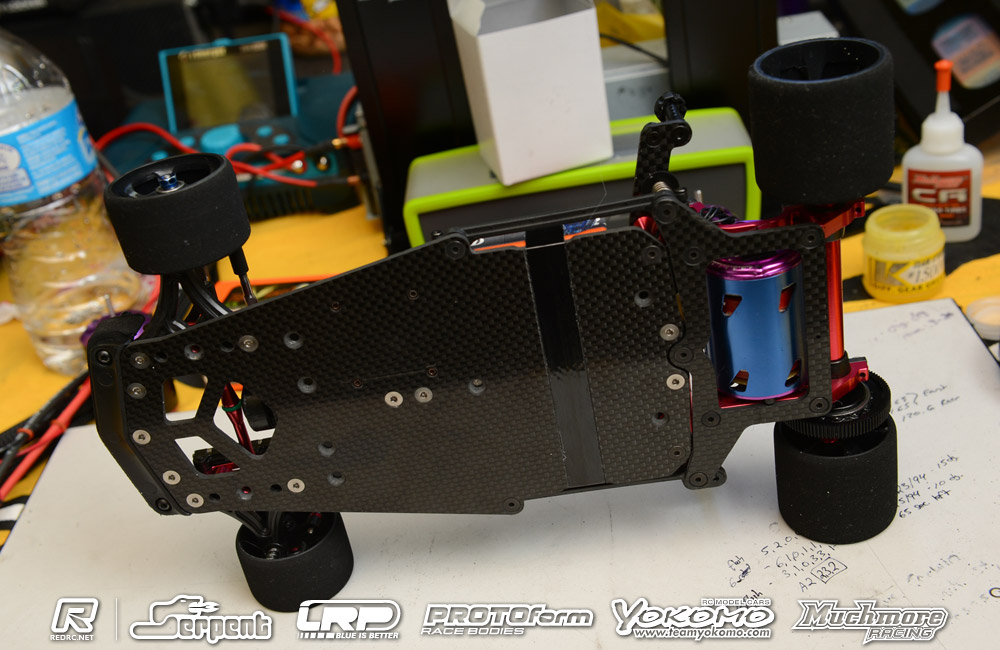
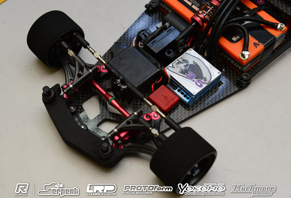
Second, where's the booster or RX battery? Is it simply removed for the pictures? Would it normally go on the deck next to the receiver? Please explain.
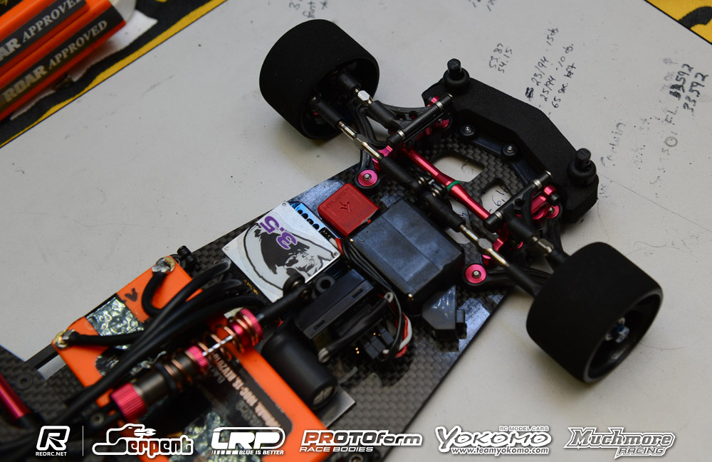
Finally, I've heard in the past that the fast TOP drivers will swap out a couple of front end parts. I believe they it's AE knuckles? I can't tell from these pics whether that's the case. What sort of hand fits are in play here? (If any.)
Oh, and double final. BSR blues front/rear?
Second, where's the booster or RX battery? Is it simply removed for the pictures? Would it normally go on the deck next to the receiver? Please explain.
Finally, I've heard in the past that the fast TOP drivers will swap out a couple of front end parts. I believe they it's AE knuckles? I can't tell from these pics whether that's the case. What sort of hand fits are in play here? (If any.)
Oh, and double final. BSR blues front/rear?
10-26-2014, 03:14 PM
#1195
Donny's cars have some really nice millwork.
For the ESC -- carbon chassis is milled with the chassis acting as the bottom plate.
Another milling feature is putting a 1/2mm cut into the front arm mount area -- cut for the shorter track width -- to prevent the front end from tweaking after a big hit.
I didn't pay attention to his steering blocks. I run ase 10l/12l. Don't see that changing anytime soon...
10-26-2014, 09:42 PM
#1196
Hey yea guys the chassis was cut to replace the plastic bottom of the case. The pocket that the internals of the speedo sit in is about 2mm in depth. Flex analysis was almost identical to stock once the speedo was tightened down. It works well and the speedo ends up only being 11mm tall. I don't run a booster or Rx pack. Also, I use associated r5 steering blocks. Hope this helps. Any other questions just ask. Thanks
 10-27-2014, 12:37 AM
#1199
Hey yea guys the chassis was cut to replace the plastic bottom of the case. The pocket that the internals of the speedo sit in is about 2mm in depth. Flex analysis was almost identical to stock once the speedo was tightened down. It works well and the speedo ends up only being 11mm tall. I don't run a booster or Rx pack. Also, I use associated r5 steering blocks. Hope this helps. Any other questions just ask. Thanks
(it just occurred to me the case is screwed together, so you could just use the same screws doh!)
Last edited by avs; 10-27-2014 at 06:34 AM.
10-27-2014, 05:52 AM
#1200
Kinda a silly rule. They allow any type of car, tires, and ESC's but not motors or batteries.
EA