


explanation of electrical current needed, *smart people look*
 04-15-2013, 06:13 PM
#16

Load depends on your traction and efficency.. Current follows a path less resistance that's why connection are super important expecially in a two lipos setup. . Matching your motor is super important verse gearing this will raise your draw and kill lipos.. That's why it's important to run a Good C rating so it can handle the draw and lower temperature.. If you have a proper setup your system flows easier without a component too compensating. AMP details are normal under rated on specifications are good gear. you will never maximize on a continuous level.. Obviously if you run a lower specified speedo with a high draw setup you will over heat and brown out causing heat and damage.
 04-15-2013, 06:18 PM
#17
Tech Adept
not to mention you will probably break a motor designed for 2s if you run it on 4s. most likely you will be changing the motor...
04-15-2013, 07:34 PM
#18
I don’t believe I ever stated that, the amps do change as the battery discharges.
No, the amps are lower for the 6V battery than for the 8.4V battery. Assuming everything else is the same, motor, gearing, RC, surface being driven on, etc.
The lower voltage battery will drive fewer amps to the motor. Power (watts) is voltage times amps so power also drops, and at a faster rate than either voltage or amperage alone.
The 250 watt motor rating is at a specific set of conditions including voltage. As voltage changes it won’t be a 250 watt motor anymore.
I wasn’t saying that, even though it is true to an extent. But a 17.5 blinky (original subject of this thread) isn’t going to approach the amp limits of a typical lipo. I’m saying the voltage drops as the battery discharges. Which drives less amps and less power to the motor as described above.
The amps do not increase as the battery discharges, it’s not a constant power situation. As the battery discharges the RC has less punch-power and speed. The drop off is less dramatic with lipo batteries than with nicad or nimh batteries for example, but it is still there.
Are you saying a 250 watt motor running on a 8.4v battery and another on a 6.0v battery pull the same amps?
The lower voltage battery will drive fewer amps to the motor. Power (watts) is voltage times amps so power also drops, and at a faster rate than either voltage or amperage alone.
The 250 watt motor rating is at a specific set of conditions including voltage. As voltage changes it won’t be a 250 watt motor anymore.
Or are you saying the battery can supply less than when fully charged? Just because a battery isn't at 100% capacity doesn't mean it can't still cope with demand does it?
The amps do not increase as the battery discharges, it’s not a constant power situation. As the battery discharges the RC has less punch-power and speed. The drop off is less dramatic with lipo batteries than with nicad or nimh batteries for example, but it is still there.
04-16-2013, 06:54 AM
#19
Tech Adept
I don�t believe I ever stated that, the amps do change as the battery discharges.
No, the amps are lower for the 6V battery than for the 8.4V battery. Assuming everything else is the same, motor, gearing, RC, surface being driven on, etc.
The lower voltage battery will drive fewer amps to the motor. Power (watts) is voltage times amps so power also drops, and at a faster rate than either voltage or amperage alone.
The 250 watt motor rating is at a specific set of conditions including voltage. As voltage changes it won�t be a 250 watt motor anymore.
I wasn�t saying that, even though it is true to an extent. But a 17.5 blinky (original subject of this thread) isn�t going to approach the amp limits of a typical lipo. I�m saying the voltage drops as the battery discharges. Which drives less amps and less power to the motor as described above.
The amps do not increase as the battery discharges, it�s not a constant power situation. As the battery discharges the RC has less punch-power and speed. The drop off is less dramatic with lipo batteries than with nicad or nimh batteries for example, but it is still there.
04-16-2013, 01:51 PM
#20
Although it is true that the impedance of the motor limits the amount of current driven by the battery voltage.
I wasn't suggesting that as the battery discharges it gets a higher C rating, i was saying that as the battery discharges the motor is going to need more current since the voltage drops.
Another example, would a RC have the same power and speed with a 1S lipo compared to a 2S? That is what you are suggesting, the motor would somehow pull twice the amps at the lower battery voltage and maintain the same power level. Simply not going to happen.
04-16-2013, 06:45 PM
#21
Tech Adept
Perhaps a moot point, getting off subject a little, but a common misconception. Current flows in the ESC and motor circuit because of the electromotive force (emf), measured in volts, of the battery, the power source. The wire in the motor windings is passive, there is no power, or force, or any other mechanism to draw current.
Although it is true that the impedance of the motor limits the amount of current driven by the battery voltage.
That is incorrect. The amps will drop with the lower battery voltage. Think about it, with your scenario the RC would never slow down when the battery ran down. That is not what happens, the RC slows down as the battery dies off. The power drops off, it is not constant.
Another example, would a RC have the same power and speed with a 1S lipo compared to a 2S? That is what you are suggesting, the motor would somehow pull twice the amps at the lower battery voltage and maintain the same power level. Simply not going to happen.
Also, I never said the motor would be as *fast*. Max RPM would obviously drop. I really don't notice a difference in power, just speed up until the lipos are almost fully discharged. I made the distinction here... So since this is my observation, it led me to the question... i'm probably too far off topic now anyway...
04-16-2013, 09:39 PM
#22
It�s certainly possible to overload the battery. Lipos have a lot of power capability, but it�s not unlimited. Perhaps we can agree that it is a system where all parts should be considered including how they interact with each other.
Agree the power drop off is not as noticeable with lipos compared to previous batteries. Especially with many modified setups, difficult to notice the drop off when one has tons of power to begin with.
Agree the power drop off is not as noticeable with lipos compared to previous batteries. Especially with many modified setups, difficult to notice the drop off when one has tons of power to begin with.
04-17-2013, 07:23 AM
#23
Tech Adept
It�s certainly possible to overload the battery. Lipos have a lot of power capability, but it�s not unlimited. Perhaps we can agree that it is a system where all parts should be considered including how they interact with each other.
Agree the power drop off is not as noticeable with lipos compared to previous batteries. Especially with many modified setups, difficult to notice the drop off when one has tons of power to begin with.
Agree the power drop off is not as noticeable with lipos compared to previous batteries. Especially with many modified setups, difficult to notice the drop off when one has tons of power to begin with.
04-17-2013, 11:57 AM
#24
Tech Adept
Out of curiosity I looked into this a little more, see if I could provide a rough estimate of the power difference. Those ESC resistance numbers seemed fairly high, so I used the popular Tekin RS and RS Pro ratings of 0.0003 and 0.00015 ohms for brushless operation.
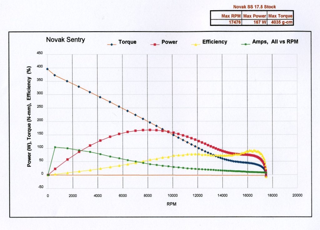
Note from the typical 17.5 dyno chart amps can vary from around 100A at low RPM to around 25A at high RPM. Have to pick a battery voltage, lets assume a nearly full charged 2S can maintain 8V under the 25 amp load and 7.4V under the 100amp load to the ESC (Starting voltage of 8.2V, IR of 8 milli ohms).
At the 100A load, the delta of the voltage drop is 0.015V, the power delta is about 0.41%.
At the 25A load, the delta of the voltage drop is 0.00375V, the power delta is about 0.094%.
If the ESC resistance numbers were as high as the numbers you mention, the power deltas would be about 9% and 1.9% respectively.
Voltage drop accross the battery terminals is not just the battery resistance with the ESC resistance there is also a capacitor in that circuit. The reason the voltage drop is because under load the transistor in the ESC actually will try and pull AC voltage from the battery. Now its impossible for a Lipo to produce a harmonic waveforms (AC voltage). This AC voltage the esc needs to drive the motor is referred to as noise or unwanted harmonics.
The resistance of the battery will never change as a function of voltage frequency because its a DC source. But the capacitor Impedance actual varies based frequency of the voltage waveform being applied to it.
So in a DC (no frequency change/not AC voltage) the capacitor has an infinite impedance. Thus the cap will charge base of the voltage being applied but does not act as a resistor.
In AC the capacitor impedance with increase as the frequency of the voltage applied increases.
Now hey this is a lipo battery only DC right. Yes correct but remember when you slam on the throttle the ESC will need harmonic current (AC) from a DC battery that the battery can't provide it. This is where the capacitor comes in. That harmonic current that the ESC needs will be supplied through the charged capacitor and not the battery because it the capacitor impedence is not infinite at high frequency. Where as the battery impedance at high frequencies is much higher then the capacitor.
This is the same concept in car amps. Yes those huge farad capacitors on 10,000w subs. A subwoofer hitting hard that is being driven by a amp is compareble to a motor and ESC being driven hard.
Glitch buster caps work in the same way. They provide harmonic current that the BEC can't provide and prevents brown outs.
So what does all this really mean.
A cheapo 45amp HW ESC with a cap accross the battery terminals will have similar voltage drop to the Speedpassion Reventon with the same motor. This is also the reason people can take a GTB2 in blinky classes and be just as fast as the guy running an RSpro.
If anything I wouldn't worry about the resistance of a ESC. The values they publish only really show how much heat is going to be produced by the ESC. They do not directly compare with voltage drop under load.
BTW here is the full eqution for Ohm's Law with a capacitor applied to it. You can see that it is a 1st order differential equation. The wiki article explains capacitor impedance better then I can. I also attached the RLC circuits ohms law equation. You can see in DC circuitry once you add a cap or inductance (i.e. motor load) that math gets complicated extremely quickly.
04-17-2013, 01:18 PM
#25
Tech Fanatic
iTrader: (13)
^ Math is fun. Next up, Ferroresonant Transformers!
Good info for those who are wondering a little more about the way our favorite motors work. Turning DC into an Almost-Harmonic Waveform (AC, Mostly!) without the help of Transformers is pretty neat electronic Voodoo.
Reading up on Stepper Motors is also another good bit of information about how these motors work, as that's what they essentially are.
04-17-2013, 02:45 PM
#26
Tech Adept
^ Math is fun. Next up, Ferroresonant Transformers!
Good info for those who are wondering a little more about the way our favorite motors work. Turning DC into an Almost-Harmonic Waveform (AC, Mostly!) without the help of Transformers is pretty neat electronic Voodoo.
Reading up on Stepper Motors is also another good bit of information about how these motors work, as that's what they essentially are.
Good info for those who are wondering a little more about the way our favorite motors work. Turning DC into an Almost-Harmonic Waveform (AC, Mostly!) without the help of Transformers is pretty neat electronic Voodoo.
Reading up on Stepper Motors is also another good bit of information about how these motors work, as that's what they essentially are.
BTW DC-AC transformers do not exist. Everything that is DC-AC is solid state. Now back in the day when High Voltage DC was introduced they used mercury arc valves to go from DC to AC. Thats some old tech there but worth a google search if you are interested.
 I was just speaking of the black magic that goes into the Ferroresonant Transformer, and that it's a lot easier to make AC from DC if you just sling DC into a transformer via PWM&PFM.
04-17-2013, 05:50 PM
I was just speaking of the black magic that goes into the Ferroresonant Transformer, and that it's a lot easier to make AC from DC if you just sling DC into a transformer via PWM&PFM.
04-17-2013, 05:50 PM
#28
As I see it most commonly used perhaps PWM doesn�t come into play, as it was a WFO analysis, the duty cycle as used for part throttle operation isn�t there I don�t believe. There would be the switching noise from the phase switching, which is at a lower frequency. Obviously both would have higher frequency harmonics, these aren�t sine waves in either voltage or current for sure.
Voltage drop accross the battery terminals is not just the battery resistance with the ESC resistance there is also a capacitor in that circuit. The reason the voltage drop is because under load the transistor in the ESC actually will try and pull AC voltage from the battery. Now its impossible for a Lipo to produce a harmonic waveforms (AC voltage). This AC voltage the esc needs to drive the motor is referred to as noise or unwanted harmonics.
The resistance of the battery will never change as a function of voltage frequency because its a DC source.
The resistance of the battery will never change as a function of voltage frequency because its a DC source.
But the capacitor Impedance actual varies based frequency of the voltage waveform being applied to it.
So in a DC (no frequency change/not AC voltage) the capacitor has an infinite impedance. Thus the cap will charge base of the voltage being applied but does not act as a resistor.
In AC the capacitor impedance with increase as the frequency of the voltage applied increases.
So in a DC (no frequency change/not AC voltage) the capacitor has an infinite impedance. Thus the cap will charge base of the voltage being applied but does not act as a resistor.
In AC the capacitor impedance with increase as the frequency of the voltage applied increases.
Now hey this is a lipo battery only DC right. Yes correct but remember when you slam on the throttle the ESC will need harmonic current (AC) from a DC battery that the battery can't provide it. This is where the capacitor comes in. That harmonic current that the ESC needs will be supplied through the charged capacitor and not the battery because it the capacitor impedence is not infinite at high frequency. Where as the battery impedance at high frequencies is much higher then the capacitor.
The current coming from the battery and cap combination have a significant DC component from the battery, an offset to the AC if you prefer. A little switching noise, which is reduced by the cap, hardly overcomes or negates the battery as the dominate power source in driving the RC.
A fun experiment that everyone can try at home, hook up the battery and charge the cap up. Then disconnect the battery, see how far and fast the charged cap can drive the RC. Unhook the servo to avoid that parasitic drain, use a receiver battery even.
This is the same concept in car amps. Yes those huge farad capacitors on 10,000w subs. A subwoofer hitting hard that is being driven by a amp is compareble to a motor and ESC being driven hard.
Glitch buster caps work in the same way. They provide harmonic current that the BEC can't provide and prevents brown outs.
So what does all this really mean.
A cheapo 45amp HW ESC with a cap accross the battery terminals will have similar voltage drop to the Speedpassion Reventon with the same motor. This is also the reason people can take a GTB2 in blinky classes and be just as fast as the guy running an RSpro.
If anything I wouldn't worry about the resistance of a ESC. The values they publish only really show how much heat is going to be produced by the ESC. They do not directly compare with voltage drop under load.
Is it a big difference, no, but it does exist for anyone interested.
BTW here is the full eqution for Ohm's Law with a capacitor applied to it. You can see that it is a 1st order differential equation. The wiki article explains capacitor impedance better then I can. I also attached the RLC circuits ohms law equation. You can see in DC circuitry once you add a cap or inductance (i.e. motor load) that math gets complicated extremely quickly.
Good conversation. The last one I had this detailed on this subject the member wouldn�t even acknowledge the existence of inductance and impedance. He was adamant that a few inches of wire in a winding was exactly equivalent to the same in a motor lead, because they were the same resistance, lol.
04-17-2013, 05:52 PM
#29
Yes exactly, stepper motors and drives are a little different. Step drives require a variable DC voltage source. This is to keep the voltage-frequency ratio during operation. The ESC used today are PWM variable drives. They produce a different set of harmonics but do not need a variable DC voltage supply.
BTW DC-AC transformers do not exist. Everything that is DC-AC is solid state. Now back in the day when High Voltage DC was introduced they used mercury arc valves to go from DC to AC. Thats some old tech there but worth a google search if you are interested.
BTW DC-AC transformers do not exist. Everything that is DC-AC is solid state. Now back in the day when High Voltage DC was introduced they used mercury arc valves to go from DC to AC. Thats some old tech there but worth a google search if you are interested.
04-18-2013, 05:40 AM
#30
Good conversation. The last one I had this detailed on this subject the member wouldn’t even acknowledge the existence of inductance and impedance. He was adamant that a few inches of wire in a winding was exactly equivalent to the same in a motor lead, because they were the same resistance, lol.
http://www.rctech.net/forum/radio-el...ng-length.html
In the linked thread, inductance was acknowledged, but its inclusion was not necessary to answer the question posed.
Yes, for the purposes of this discussion, the resistance of the wire external to the motor is equivalent to the resistance inside the stator, since in a Y-wind they are in series.