


Dyno, Homemade, Using a Novak Sentry Data Logger, Continued, The Experimental Thread.
 04-17-2009, 10:09 PM
#46

A lot of unknows there for us RC guys.
Making the Steel Flywheel
With Apologies to Matt's Machinist I am going to describe a couple techniques to get a good flywheel. I know of one reader of this thread who is also making up a flywheel. What you want is no up and down motion of the outer edge (no radial runout), No side to side or wobble motion of the edge (axial runout of the edge), and then a balancing to correct for the holes we have to put in it to secure it to a 1/8 inch shaft.
It is not too much trouble getting the disk right. The trouble is making an exact size hole that is perpendicular to the work. You could do this on the drill press at the expense of some radial runout, but it really should be done on the lathe.
The hole in Matts flywheel was oversize. No doubt about it. This caused considerable lateral runout and vibration and harmonics as the flywheel spun up to speed on a motor. The hole was bigger than the worn hole in the Aluminum flywheel that I have. I repaired the Aluminum flywheel with a punch. I tried peening the steel one down to size with a center punch but it was just too far away from .125. Chances are the hole was made in one pass with a 1/8 drill after a center punching. A drill always drills 1 or 2 thousandths over size. A drill also tends to wander a little unless you have a good deep center hole. So here is a good procedure.
I had to fix the hole, so I first drilled it about .25 inch, bored it .374 and then hammered a new piece of stainless into the press fit hole. I then faced the rod flat after cutting it close with a parting tool. I left the rod long for a longer bearing surface on the shaft.
Chuck the flyweel in the outside jaws of your 3 jaw chuck.
use a .110 center drill to start the hole. Drill it as deep as you have the .110 stem sticking out of the center drill. This drill has a nice fat shank. It is short and very stiff. It keeps the point from wandering as you start the drill. Yes it is absolutely essential for this hole.
Now take a short jobbers length cobalt drill and drill the hole to .120 inch. This is .005 undersize. Now put in your chucking .125 reamer and pass it quickly in and out of the hole. You don't want to leave it in there to remove extra material. Now you have a hole within .0001 inch of .125. the hole tends to that very slight amount to oversize. Undersize reamers are also available for press fits.
The fit on the motor shaft was now very snug. A light tap with a small wooden handle was used for the first install. Now it is a light drag fit. Perfect. Radial runout was nonexistant now. Axial runout .001-.002 by eye depending on the condition of the motor shaft. Excellent. This is a 10 fold reduction. I rebalanced it on my prop balancer. I ran it up to full speed on my 13.5 with much better sounding results. This will relieve stress on the motor bearings and give a more true value to the Dyno.
I passed the reamer by hand through the hole again after tapping the hole for a new set screw, #8 x 32 TPI .
Mass very slightly lower at 365 g
diameter of OD 3.426 inch
Inertia 3.4549 x 10⁻⁴ kgm^2/s^2
For the sentry this flywheel seems to be essential for the stock motors, 21.5, 17.5, 13.5. Then I would change to the aluminum flywheel for the more powerful motors.
Last edited by John Stranahan; 04-18-2009 at 09:33 PM.
 04-17-2009, 11:34 PM
#47
System Theory:
I have and use a crude Chassis data tracker that basically uses a load motor with a resistor and drives off an axle Tire to Tire w/ my car.
I use gear ratio on the slave motor pod to achieve the desired amp draw...and set that amp draw based on actual runs on the track w/ the EagleTree eLogger.
Using the data I have right now based on my most recent test runs...
Fresh Charged ORION 3200 LIPO - heated to 120 degrees. Static Voltage 8.42v
Motor NOVAK 21.5 Brushless
On the track this car ran the 820ft velo at the fastest lap of 10.28 seconds, and the next several laps at 10.5-10.6 seconds.
This same setup on the Chassis "dyno" (with the heated/charged battery)
10,500 rpms (round numbers) @ 8.2 volts / 16.8 amps
Geared 73/60
Axle RPM 8630 - (On the Dyno)
Tire Diameter 2.448" (0.64088')
820 ft. (approx run line) / 1279.5 Tire Revaloutions Per Lap
1279.5 trpl / 10.5 (seconds per lap)= 121.855 Tire Rotations Per Second x 60 = 7311.30 Axle RPM's needed
8630 - 7311.30 = 1318.70 RPMs LOST (due to aero and other factors)
These are not scientific numbers, they just appear to be the numbers in relation to the chassis dyno I'm using.
Each run gets the data a little more fine tuned.
04-18-2009, 12:28 PM
#48
Tech Adept
John, great work on the flywheel advice for using with the Sentry and in general.
SWTour:
Thanks for the information on your gearing approach. It sounds like a reasonable attempt to simulate the equilibrium load at racing speed, where heat, driveline friction, and aero losses are to a degree unknown (wildcards).
I am not sure how you decide what current you want to draw? Can you adjust the equilibrium rpms on the Dyno, and if not, would it help your tuning efforts to do so with an adjustable brake resistor or mechanical brake?
I looked for a good photo or diagram of the Velodrome on SWT web site but didn't find one. I am picturing high banked U-turn corners and long straights.
I have a detailed specification here for the 2008 Dodge Viper Coupe. The Mythbusters race this downhill against a 1/64 car in the episode Big Car versus Little Car. It is actually an interesting study in scale down Physics.
I am going to estimate the power of a Viper pushing air at full scale and 1/10 scale as a power versus velocity curve. I'll plot this from zero mph up to some reasonable value at each scale and post results if they "make sense."
04-18-2009, 02:49 PM
#49
John, great work on the flywheel advice for using with the Sentry and in general.
SWTour:
Thanks for the information on your gearing approach. It sounds like a reasonable attempt to simulate the equilibrium load at racing speed, where heat, driveline friction, and aero losses are to a degree unknown (wildcards).
I am not sure how you decide what current you want to draw? Can you adjust the equilibrium rpms on the Dyno, and if not, would it help your tuning efforts to do so with an adjustable brake resistor or mechanical brake?
I looked for a good photo or diagram of the Velodrome on SWT web site but didn't find one. I am picturing high banked U-turn corners and long straights.
I have a detailed specification here for the 2008 Dodge Viper Coupe. The Mythbusters race this downhill against a 1/64 car in the episode Big Car versus Little Car. It is actually an interesting study in scale down Physics.
I am going to estimate the power of a Viper pushing air at full scale and 1/10 scale as a power versus velocity curve. I'll plot this from zero mph up to some reasonable value at each scale and post results if they "make sense."
SWTour:
Thanks for the information on your gearing approach. It sounds like a reasonable attempt to simulate the equilibrium load at racing speed, where heat, driveline friction, and aero losses are to a degree unknown (wildcards).
I am not sure how you decide what current you want to draw? Can you adjust the equilibrium rpms on the Dyno, and if not, would it help your tuning efforts to do so with an adjustable brake resistor or mechanical brake?
I looked for a good photo or diagram of the Velodrome on SWT web site but didn't find one. I am picturing high banked U-turn corners and long straights.
I have a detailed specification here for the 2008 Dodge Viper Coupe. The Mythbusters race this downhill against a 1/64 car in the episode Big Car versus Little Car. It is actually an interesting study in scale down Physics.
I am going to estimate the power of a Viper pushing air at full scale and 1/10 scale as a power versus velocity curve. I'll plot this from zero mph up to some reasonable value at each scale and post results if they "make sense."
What about using a prop instead of a fly wheel?
04-18-2009, 03:10 PM
#50
And here's another idea... anyone ever try to create a chassis dyno? In the full scale world engine dynos and chassis dynos tell two different stories.
I'm sure not all TC drivetrains are created equal. It'd be interesting to see how much of this power actually hits the road.
04-18-2009, 03:41 PM
#51
What you would like in a dyno is reproducibility to be able to tell apart two different items. When you add a prop the air density becomes a variable. Tip speeds on the prop approach 500 mph or so. This air density from day to day becomes a variable.
A chassis dyno has similar problems. It would tell you the condition of the chassis, but repetitive readings would be less precise due to the sloppy nature of outdrives, non centered axles, Narrow bearing placement at the wheel. Everthing runs in a sloppy manner compared to your fullsize car. Imagine grabbing the spindle on your full size car and moving it over an arc of 5-6 degrees by hand. You would certainly not drive it this way. You could turn this rig into a chassis dyno by linking it to a set of four coupled rollers for 2 and 4 wheel drive. Lot's of machine work there. The Sentry could easily sense the roller RPM with the magnetic sensor setup that is included.
In stock truck it would not take long for the gears in the tranny to wear to the point it hurt lap times. It helped a lot to lube those internal gears regularly with a homemade port.
My 1.0.5 motor suffered some problem with the sensors. It will be a slight delay before I have one again. I have a little voltage series I am going to run next. A 13.5 on 4,5 then 6 cell. I have my antique Tekin chargers out charging those puppies up.
04-18-2009, 04:55 PM
#52
A chassis dyno is do-able though. I plan on making one for our track using the Novak Sentry and charging a buck or two to dyno the cars, no 4WD dyno though, just 2WD for offroad. Thanks for fixing my flywheel John, things get scary hooking that up to the larger motors.
I sure hope Novak is looking at this thread and incorporates somehow the dyno program into their official Sentry software.
I sure hope Novak is looking at this thread and incorporates somehow the dyno program into their official Sentry software.
04-18-2009, 05:54 PM
#53
Tech Adept
Attached are two graphs generated in Numerit Pro showing power versus forward velocity for the full scale Viper versus a 1/10 scale replica assuming a constant drag coefficient Cd = 0.4.
This should be reasonable at subsonic velocity considering both bodies are much bigger than air molecules. In a wind tunnel engineers use matching numbers to verify their scale down measurements, which is beyond our scope.
Scale cars will be more sensitive to track temperature impacting the actual density of air.
At RENO airport on a hot day, more than a mile above Sea Level, due to thin air with high ground temperature, a pilot told me his small plane cannot achieve take-off speed. Takeoff is possible in the morning before the ground gets hot. Landing on a long runway is not a problem since the plane converts gravitational potential energy to Kinetic Energy while it descends.
Comprehensive data for the Viper is given in the attached pdf. Gear ratios, peak power, aerodynamic factors, so it is a good resource for further study.
NASA applies a standard called Sea Level Static Air (Standard Day) as the engineering value when designing machines. It occurs at 59 degrees F and standard pressure, I think zero humidity (dry air). NASA Air Properties:
http://www.grc.nasa.gov/WWW/K-12/airplane/airprop.html
Kestrel sells a good meter to measure actual air density but it is a bit costly. Engine tuners use this kind of meter to adjust for humidity, actual pressure, and temperature. My little brother races Methanol 250 midgets and humidity has a significant impact on his carb tuning from day to night.
`Density Sea Level Static Air
rho = 2.37E-3 `{slug/ft^3}
`Dodge Viper Full Scale
vTop = 200 `{mph} top speed
Pmpk = 600 `{hp} peak power
Af = 19.3 `{ft^2} frontal area
Cd = 0.4 `{#} drag coefficient
G = 1.5 `{#} top gear ratio
r = 1.11 `{ft} tire radius
I don't have a torque-speed curve, so 200 mph top speed is taken from here:
http://www.edmunds.com/insideline/do...ticleId=122304
Note the theoretical top speed is 225{mph} if all peak engine power went into pushing air. Maximum power occurs at 6100 rpm near the redline, but the Viper turns only 3794 rpm per my calculations while investing 423 horsepower into pushing air at a top speed of 200 mph. This appears reasonable to keep the car from flying in a power slide (stock car style) and it keeps the engine from being overworked in top gear.
The second graph estimates watts invested in Drag Power versus miles per hour for a 1/10 scale Viper up to 65 mph. One of the posts around here puts the typical Cd = 0.5 for an RC car if it has a wing and makes downforce. This is a pure guess and the tradeoff is between downforce to make better time in a longer turn and streamlining to make better time in a long straight.
04-18-2009, 09:00 PM
#54
The Effect of Voltage on Brushless Motor Max Power
The stated question was whether there was an easy way to convert dyno output from one voltage to another. I did some test with the Competion Electronic dyno which controls very precisely the amperage and voltage delivered to the motor. I posted the graph in our previous thread. The result was questioned on the basis that the dyno controlled the amperage.
Here is a very similar but much more troublesome study. Instead of selecting 5 voltages on a screen, I assembled various packs from NiMH cells and also used some test with LiPo. I charged and used the NiMH cells HOT off the charger. That explains the high power produced by the six cell pack. Is it that much better on the track, well no. This high voltage drops off quickly. The test order was randomized to help eliminate time trends.
I made further improvements to the flywheel. It still had some warp in it that could not be corrected with a good true hole. I surface ground it on the lathe using the tool post grinder and the prop balancers shaft for a mandrel to turn the flywheel. I did not support the edges this time and used the grinder to take off a couple of thousandths off the three surfaces. True like the Fantom steel flywheel now, not as smooth, but it has an interesting texture. I rebalanced it. It is delightfully quiet now. I just hold the car in my hand.
There are two replicate tests, both with LiPo and my standardized battery handling procedure. Note the exact same voltage at full power on two separate days with two slightly different flywheels. You see this on the chart above the graph in the middle column of voltages near the bottom. The power outputs are reasonably close. You get a better perspective by looking how close those two close diamonds are on the graph.
It appears again that no there is not a simple formula to convert powers at different voltages. It is not a proportion. The line does not go through zero.
If you fit a quadratic (x2) the x axis intercept moves left only to two volts. You get a good fit. If you force the quadratic through zero you get a fair fit. Not quite as good as a straight line. So maybe P1/P2 = V1^2/V2^2 might be a good aproximation. Where P is power V is voltage. There is not even a hint of curvature in the data, However.
Polished Procedure.
That's all the things I wanted to do with the dyno. It is precise. You must limit the charge to a value like my Scorpion chargers first blinking green lights. I give it 3 blinks and pull the plug. I wait 10 minutes between tests for motor cooling. I charge near the end of this 10 minutes.
The digikey amp meter sensors are in the mail. I will run a couple of 3.5 tests with the new sensors.
The spreadsheet is working great now. It is not so sensitive as to where you end your data set. Max powers do not change. I suggest again to look for a stabilized voltage near full RPM (likely 8-10 identical voltages) take the first of these points and stop the data there. This is where the flywheel stops accelerating for the most part.
I am already very pleased. Wait till we get the amps nailed down with the new sensor.
Last edited by John Stranahan; 04-19-2009 at 08:08 AM.
04-18-2009, 11:35 PM
#55
Tech Initiate
This thread is facinating, even though oval and drag racing isn't relevant to a European. I do some full scale racing, and would love to apply this to my TC as well. The power curves look quite similar to a well behaved stock combustion engine, where as a racing engine will have a much narrower power band. Some of them can only be used over a 1000 - 1500 powerband, and is useless every where else. Most people will be faster with the stock engine.
With a gearbox and a datalogging system telling me apex speeds for the different turns, I can match the individual gearings to my engines power band. But for my RC racer I don't have a gearbox and I don't know my apex speeds. I would love to be able to apply this for TC racing, but I don't know how. Am I overlooking something?
Best,
Peter Knudsen
04-18-2009, 11:58 PM
#56
ST,
Here's a pic of the ENCINO VELODROME in Southern Cal - taken just a couple days ago...
This is from outside turns ONE and TWO
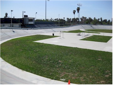
For a larger view click
http://southwesttour.com/images/velo409/track_shot.jpg
Here's a pic of the ENCINO VELODROME in Southern Cal - taken just a couple days ago...
This is from outside turns ONE and TWO
For a larger view click
http://southwesttour.com/images/velo409/track_shot.jpg
04-19-2009, 08:01 AM
#57
Joes races at a super nice facility. It will be holding some speed record runs in the near future. See the text in red below. Apply it for some maximum speeds.
Peter-If you had a Sentry data logger, you could in theory apply the same principles by getting apex speeds of the RC car on the track. I plan to do some of that later in the thread. We will see how that corresponds to dyno data from the motor and the gearing I use on the track. Note that I used the same gearing on my 13.5 for both road and oval. The road course being a large 1/8th scale track offered similar speeds. My oval gearing was selected for max power at the average speed. This is an easy concept to grab hold of.
Tests to come
Novak GTB speed control vs LRP tc edition on an LRP X12 3.5
Track Power 5400 mA-H LiPo Battery vs FMA direct 5000 mA-H LiPo
04-19-2009, 01:49 PM
#58
Tech Initiate
Hi John,
I do have a sentry data logger. I use my data logger in my full size car all the time, so I immediately bought the sentry when it came out. I haven't found much use for up to now, because it in my opinion lacks one important feature. It lacks a lap sensor, so I could compare data lap by lap.
It is of course interesting to see how temperature builds up, or how the batteries perform over 5 min. But being able to extract the data from your best lap, and being to compare steering and throttle input, RPM and G-forces to the average lap is the real value.
In theory this is possible, but not in the software included. Which means that it can't be done at the track between runs. I wish they would have worked together with one providers of professionel data logging software,instead of doing their own software.
Thanks for the input on gearing, I will give it a try.
Best,
Peter
04-19-2009, 03:15 PM
#59
Very interesting indeed.
And here's another idea... anyone ever try to create a chassis dyno? In the full scale world engine dynos and chassis dynos tell two different stories.
I'm sure not all TC drivetrains are created equal. It'd be interesting to see how much of this power actually hits the road.
And here's another idea... anyone ever try to create a chassis dyno? In the full scale world engine dynos and chassis dynos tell two different stories.
I'm sure not all TC drivetrains are created equal. It'd be interesting to see how much of this power actually hits the road.
Looks cool and works very well.
 04-19-2009, 05:10 PM
#60
John,
I build a really crued "chassis dyno" based off the idea of the old THOR/PSE Chassis dyno built over a dozen years ago.
Having the tracking systems like the EagleTree E-Logger and the NOVAK Sentry make the need for anything super exotic a thing of the past.
I use a pan car POD-AXLE-HUBS-T Plate-Wheels and Tires (Wide CAPPED Tires)
Installed in the pod is a STOCK/27t BRUSHED motor, shorted the +/- terminals with a resistor (I forget what Ohm rating...something I had around the house I'm sure...)
For my motor, I'm using a 4:1 gear ratio to the axle. (I adjusted the ratio to get the desired load @ the RPM I was testing.)
The T PLATE/POD is bolted to my Scale Table (Chassis Scales) so that car sits on the tires, forward of center to eliminate the bounce (that was created sitting directly on top)
As far as what we started with for AMP LOAD and RPM etc. That was derived by actually running the car in race trim - WITH the E-Logger in the car. This let us see the RPM , VOLTAGE and AMP load used under race conditions.
Then the dyno was set up to duplicate those parameters.