So many topics about iChargers and high current discharge banks that made me think to give it a try. A small experimant with 10A discharge did gave some results on the internal resistance that I wanted more.
One remark: this design is only for 2S batteries but can be made for higher voltages as well.
I have no iCharger so it must be something stand alone. I have this LiPo checker/monitor
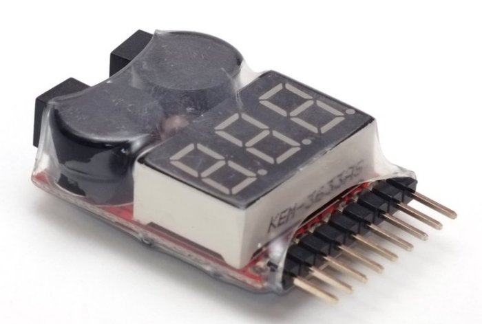
This one can be bought all over the world, it has a monitor and alarrm function. The alarm is voltage adjustable from 2.7v up to 3.8v in 0.1v steps.
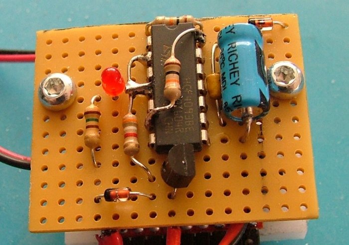
After a small investigation it seems the LiPo alarm is provided by the 2S (7.4v) connection and the LED with the 2 buzzers are switched to the ground by a simple transistor. This signal will be used to stop the discharging.
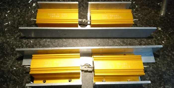
I decided to get 0.82 ohm - 100 watt resistors, I was thinking of 5 max (50A) but in a package of 6 it was cheaper to get
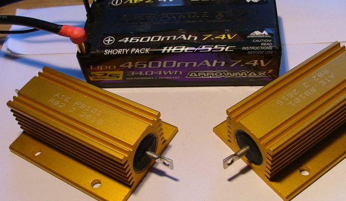
(next to a shorty LiPo)
The diagram so far
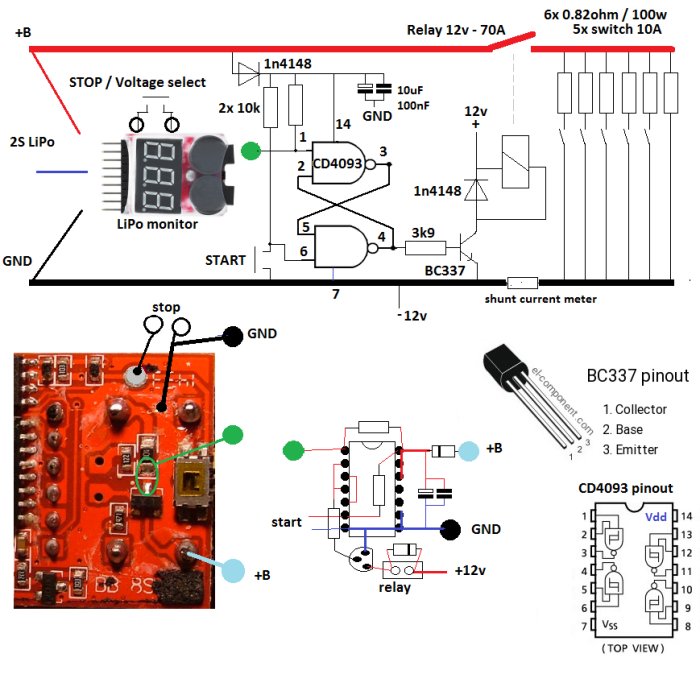
A small Set/Reset flipflop with the 2 NAND gates is the extension of the LiPo monitor. 1 push button to start and using the beep signal from the monitor to stop. The push button for the voltage select is causing a beep when pressed so it can directly used as a stop button.
Through a transistor a 12v automotive relay is powered to activate the resistor bank. The resistor bank will have 1 direct connected resistor and the other 5 are switchable, so it can be set from 10 up to 60A in 10A steps.
The shunt resistor is from a 10 dollar Ebay 100A/100v panel meter.
The relay, the panel meter and the LED lights in the 10A switches will be powered by a sepperate 12v power supply to be sure no high current will be drawn from the battery when it is stopped, only the LiPo monitor will stay powered by the battery and that is not much.
To mount the LiPo monitor as a panel meter in a case I had to remove the 2 buzzers, they will be mounted on the back side of the PCB when all wirering is done.
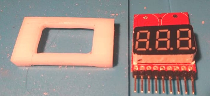
From a piece of nylon I made a tight frame arround the 3 digit display.
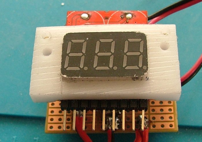
On the back with some spacers the extended electronics
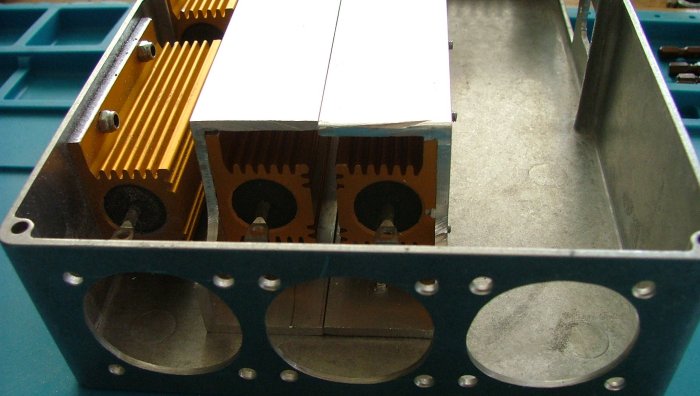
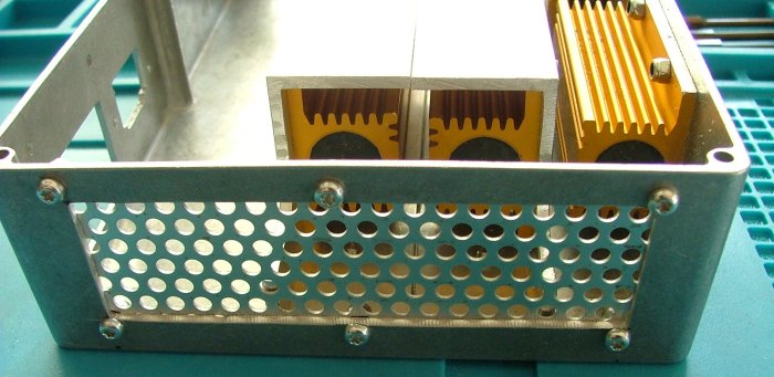
I have found an aluminium case, 2 resistors are mounted to the back and the other 4 on frames in the middle.
With on one side 3 fans will be mounted and on the other side some holed aluminium for the air intake to disipate the 500 watt max of heat.
And made some nice feets for the case:

That is so far the build, I am waiting for the switches and panel meter to work on the layout of the front panel and the left over space on the inside.