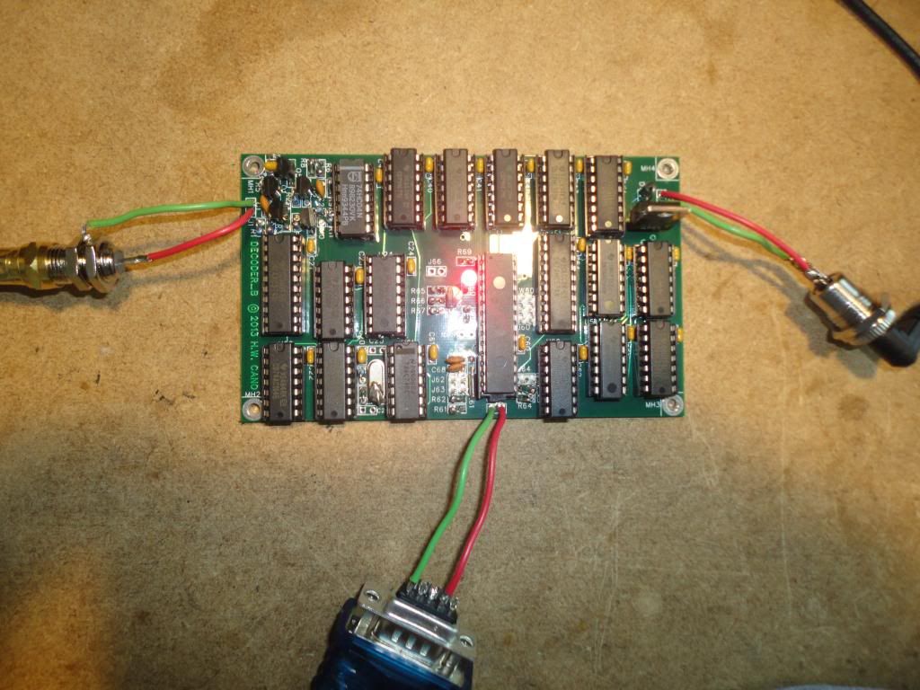
The decoder PC boards arrived yesterday, and I now have two of them running. The following corrections must be made:
Omit C25 and C26 (22pF).
The 1uF capacitor on U2 (the 7805 regulator) was mislabeled on the schematic (duplicated �C4� reference designators), and consequentially was not included on the board. The cap should be soldered directly to U2. I�ll correct the reference designator to C5 on the schematic.
The node label �3D� was misplaced on the schematic at U20A pin 3, causing the connection to be ignored. A jumper must be soldered from U20A pin 3 to U21 pin 4. I�ll fix this on the schematic also.
J1 is shown incorrectly on the schematic. The outer shield should connect to ground, and the inner conductor to R1.
Edit: This has been corrected on rev C and later of the schematic.