Introducing the Truck version of the RB6.
The proven race winning performance of the world champion RB6 is all carried on to this truck chassis!
Debut win! 2013 ROAR National Champion!
 __________________________________________________
Here are some links to important documents for the Kyosho RT6.
Build Document, click
here.
Parts List, click
here
Exploded View, click
here.
Editable Setup Sheet, click
here.
List of Setups (Look for RT6), click
here.
__________________________________________________
Optional aluminum steering parts UMW701 & UMW702 are included in the kit!
New gullwing style shock mounting postion in center. The standard holes are still available on the same arms!
Quick-change style wheel hubs front and rear. Same wheels front and rear.
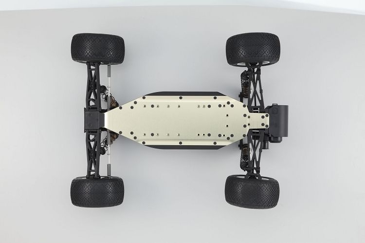
Extended truck length 7075 hard anodized aluminum chassis.
Velvet coated "Big Bore" shocks with genuine X-gear springs. New 80T spur gear and "bleeder" shock caps.
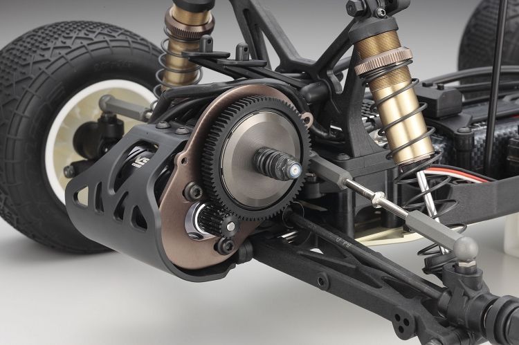
New ESC pedestal for added traction in rear motor setting.
Allows for both Mid Motor and Rear Motor configurations. All items are included in the kit.
High traction or low traction, the RT6 is ready!
Key Features
1.) 7075 Hard Anodized chassis.
2.) Allows both mid and rear motor configuration.
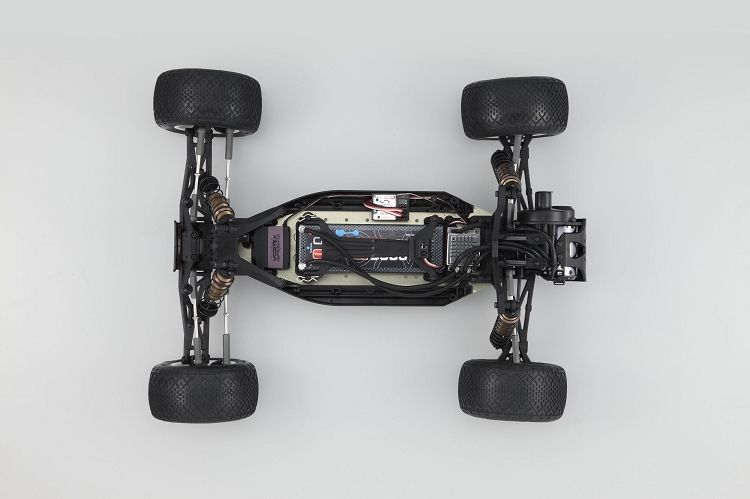
3.) Compatible with various types of battery packs. (Straight, Separate and shorty)
4.) Rear gull wing type lower suspension arm for most efficient grip.
5.) Proven RB6 steering crank system allowing linear controls. UMW701 and UMW702 are included.
6.) Velvet coated big bore shocks with new "bleeder" style caps.
7.) X-Gear Ball diff grease, hi-graphite grease and shock springs included.
8.) Various Option parts available.
9.) X-Gear Springs. (Front Red / Rear Gold)
__________________________________________________
Here are some option parts available for you.
Kyosho has released new rear suspension hangers that allow you to change the rear width and adjust rear toe on the car depending on which insert you install.
- KYOUMW705 Kyosho Aluminum Rear/Front Rear Suspension Holder for both rear and mid-motor configuration
- KYOUMW706 Kyosho Aluminum Rear Suspension Holder (Rear Motor)
- KYOUMW707 Kyosho Aluminum Rear Suspension Holder (Mid Motor)
- KYOUMW705-01 Kyosho Suspension Holder Bushing Set
__________________________________________________
Option part available.
W5303-10 Shock Piston(3x1.4/2pcs/Big Bore Shock)
Optional pistons for RB6/RT6/FS2 SP/SC-R SP big bore shocks.
3 X 1.4mm
__________________________________________________
Option part available.
W5303-11 Shock Piston(4x1.3/2pcs/Big Bore Shock)
Optional pistons for RB6/RT6/FS2 SP/SC-R SP Big Bore shocks.
4 X 1.3mm.
 __________________________________________________
Option part available.
__________________________________________________
Option part available.
W5303-09 Shock Piston(2x1.6/2pcs/Big Bore Shock)
Optional pistons for RB6/RT6/FS2 SP/SC-R SP big bore shocks.
2 X 1.6mm
 __________________________________________________
Option part available.
__________________________________________________
Option part available.
[*]UMW719 Rear Bulk Weight Set(RB6/MID MOTOR)
Rear weight set for RB6 MID, 2 - 5g pieces, and 1 - 15g.
5g-25g can be mounted in 5g increments for improved traction in low grip conditions.
Only fits UM724B rear bulkhead.
__________________________________________________
Option part available.[*]UMW718 VVC Aluminum Drive Gear (26T/MID Motor)
Velvet coated aluminum idler gear for RB6/RT6 mid motor. Frees up transmission by using plastic/metal/plastic/metal configuration.
 __________________________________________________
Option part available.
__________________________________________________
Option part available.
UMW712 Carbon Composite Front Knuckle Arm Set
Optional carbon composite steering knuckles. Increased stiffness and decreased weight realized. *NOTE* These are listed for the RB6 but since they use the same part number as the RT6 so this is a possible option.
__________________________________________________
Option part available.
UMW713 Carbon Composite Front Hub Carrier Set
Optional carbon composite caster blocks for RB6. Increased stiffness and decreased weight realized. *NOTE* These are listed for the RB6 but since they use the same part number as the RT6 so this is a possible option.
__________________________________________________
I seen a friend of mine do this for his TLR vehicle so I thought I would document my building experience with the Kyosho RT6 Truck and touch on some of the tricky parts, share with you things that I thought were important and maybe teach you something new.
As you can see below everything is packaged nicely within the box. As you probably already know the truck does not come with a body but any truck body, designed for the RC10T will work when the truck is setup as a rear motor without any major modifications. If you set it up with a mid motor configuration then you will need to get creative with the scissors and the body. Rumor has it we should see a mid motor body but from who and when I don’t know.
A little information about RC10T bodies. The RC10.1 Truck bodies have a higher hood scoop to allow greater clearance of the shock tower. The RC10.2 Truck bodies have a flatter hood scoop and it sits lower so the opportunity for it to rub on the front shock tower area is greater than the RC10.1 truck bodies.
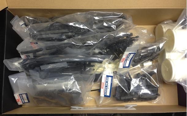
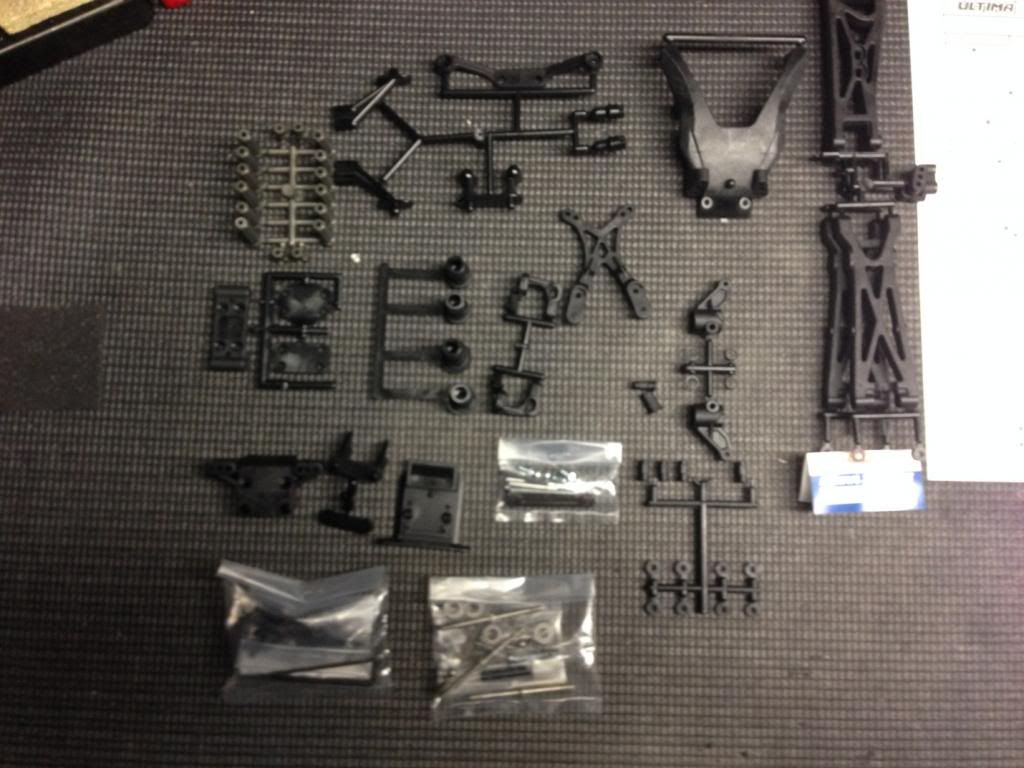
I opened the first bag and this is what you get. You will notice that there are some parts that carry over from the RB6 but not all of them. For example, the steering knuckles, caster blocks, the front top plate and camber link mount, tie-rod ends, suspension mount, skid plate, and hingepin brace.
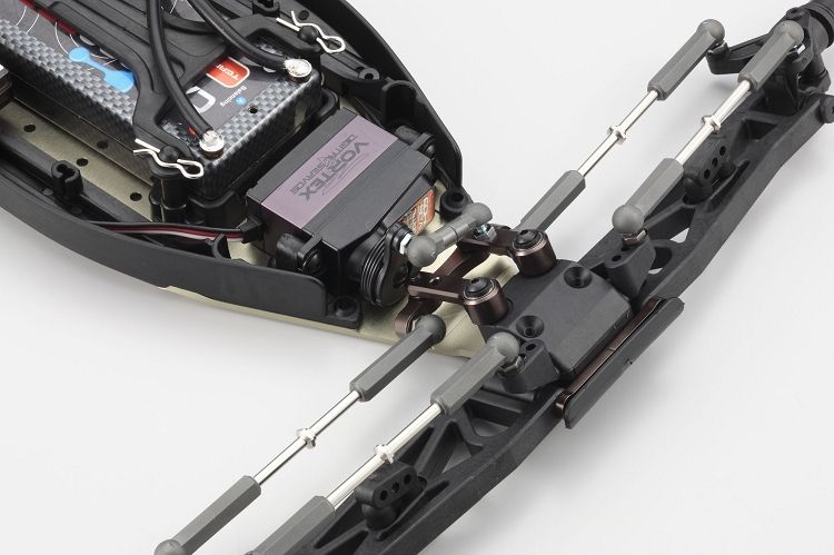
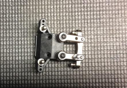
As you proceed through the assembly manual you will first build the steering bell-cranks and attach them to the front bulkhead. Pay attention to the direction of the arrow on the steering rack. It is important you install this the correct way as it will affect the handling of the truck. Refer to your manual or your setup sheet on how this will be installed. I won’t get into what it does because there are a lot of chassis setup guides out there for you to read and I don’t want to turn this into another setup thread.
Since I am talking about the steering rack assembly those of you who own the RB6 will notice that the one on the truck is all aluminum. For me, this gives me reassurance that I won’t lose steering during my run due to component failure. Now if the screw backs out of the servo horn that is a different story. When you attach the steering rack to the arms use a small amount of locktight on the screw and I do mean a small amount. This will prevent the screws from backing out. You may want to remove or do not install the ball studs in this position at this time. You will see why in the upcoming pictures.
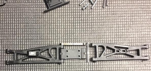
With the front bulkhead/steering assembly completed it is now time to work on the arms. The front suspension mount block is the same one that is found on the buggy.
The arms have the same shock mount as the RT5 did. With this setup you can mount it either towards the inside of the arm or the outside of the arm, again refer to the manual or setup sheet.
The front suspension mount block has a hole for set screws to go into it to help secure the inner hinge pins. My suggestion to you is to make sure you do not crank this set screw down to tight as it could strip out. When you insert the hinge pin make sure that the flat spot of the pin is lined up with the hold on the mount as it does get inserted in a specific direction.
You will notice the new aluminum hinge pin mount on the front of the truck. You can tell it is new as it has a groove in the middle of it. The first generation on the buggy of these would bend easily. After many runs on my truck and on my buggy I have not had any issues with this new version but your experience may vary. The trucks come with the second generation.
One thing that I wanted to mention is that I always run a 3.0mm reamer through the hinge pin holes that are 3.0mm in size. I do this to prevent binding when the arm moves up and down. The same thing can be said for the caster blocks but since the hinge pin doesn't go all the way through the arm I insert it until it stops and then remove it. I also do this to the caster blocks and rear hubs and arms. Basically, anyplace there is a 3.0mm hinge pin I run the reamer through it.
Now I have gone ahead an assembled the two pieces together and am getting ready to attach them to the chassis. Here is one tip that some people used to do and that is put a chunk of lead in the bottom of the front bulkhead. What does this do? Well a good friend used this analogy, when you go to a grocery store throw a case of your favorite beverage on the bottom rack of the shopping cart and then feel how it reacts. This is extreme but at 1/10th scale it can give you an idea of what it does. For this build, and it isn't listed in the manual or setup sheet I didn't add the weight.
Now when you assemble these pieces to the chassis you have the choice of adding a spacer between it and the chassis. This too affects the handling of the truck but it wasn't listed on my build documents so I left it out for now.

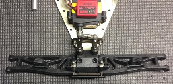
Next up is the installation of the servo. It is very important that you get the linkage between your servo and the steering arms correct. When the servo is centered you want the steering rack to be equal left to right. That means you don’t want it to favor one side or the other.
Here are some tips that I found to be useful. Hook up your servo to a working radio system so you can set the neutral point or the middle of the servo throw. Don’t let that be your last step otherwise you risk the chance of having to take things apart again and fix it. I also recommend a small amount of lock tight on the screw as well since you don’t want that to back out either.
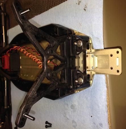
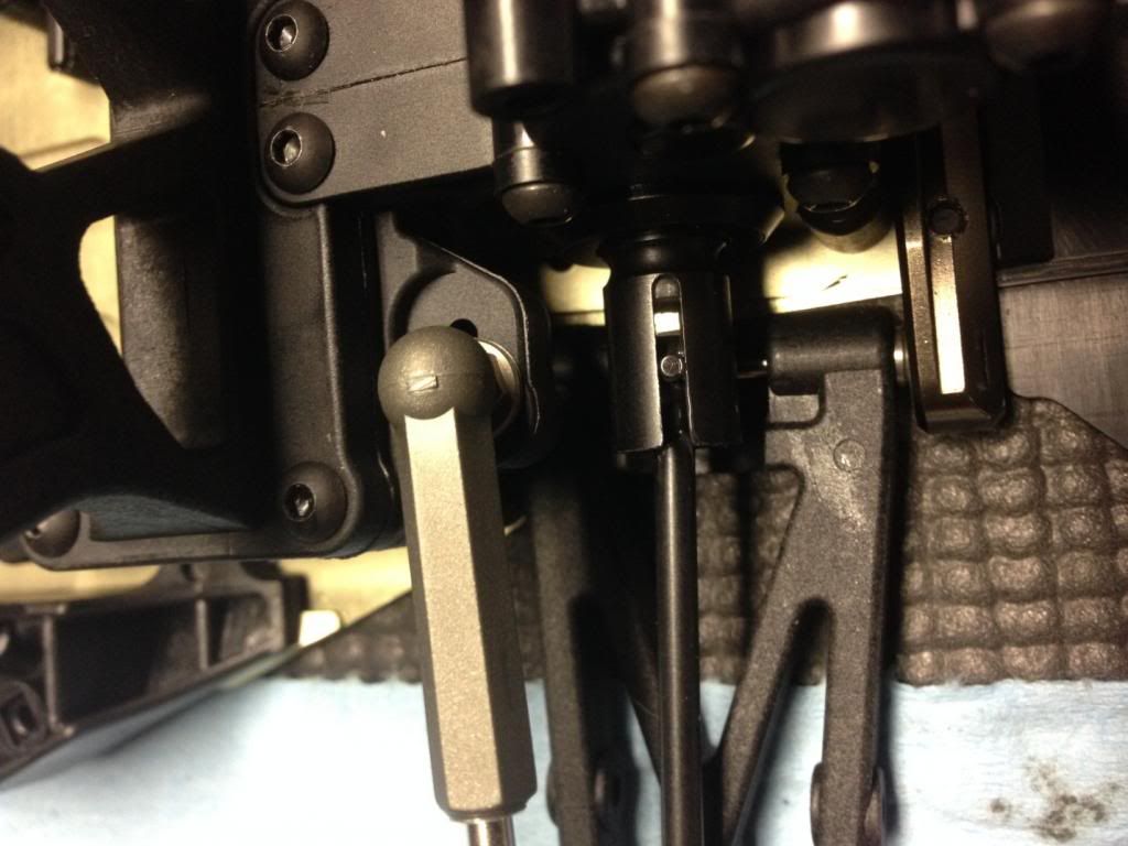
Now it is time for the top plate for the front bulkhead. The latest version of the bulkhead has resolved the clearance issue of the steering assembly that was found on the RB6. So there really isn't any grinding needed except for the piece shown in the picture. Remember always use a sharp blade and cut away from you. If you use a dull blade you will use more force to cut something and thus increasing the chance for injury if you are not careful. Thus the reason why you use a sharp blade and cut away from you. If you use a Dremel or some other sort of power tool I cannot stress enough to use safety glasses when you perform the removal procedure. Take it from me, you don’t want to get hit in or near the eye with something as it is very uncomfortable
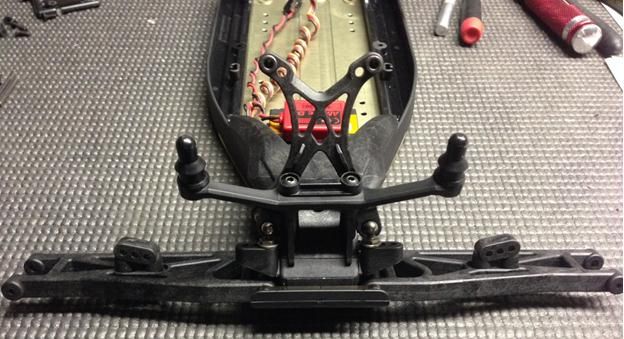
Now it is time to put all of the plastic pieces together for the front end. I have added the plastic side pieces to the chassis, placed the top front bulkhead on the chassis and screwed it into place. I then attached the front shock tower and body mounts to that piece.
When you look at the picture you will notice two things. First is the extra screws to the left. These screws go in the plastic side pieces that run down the chassis of the truck. The more screws you add the stiffer/less flex the chassis will have. This is a nice tuning option if you run on a high bite track. For low bite tracks you might want to remove some screws to see how it responds.
The second thing is the socket head screws for the front shocks. If you plan on running a body made for the RC10.2T then I suggest you replace those socket head screws with button head screws. The reason being is that it has the chance to rub on the body and scuff up your paint. You could also place a sticker over that part too but I eventually changed out the screws.
Here is a picture of the front end. You can see I have the ball studs for the front camber links installed and they are right in line with one of the bottom screws on the shock tower. So I had to remove them and then install the bottom screw of the shock tower. Not a major setback but still something that I had to revisit.
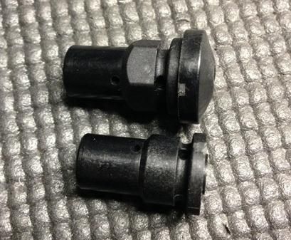
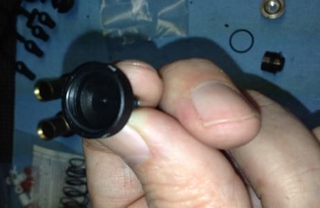
Next up is the steering block assembly. Just like the RT5 the RT6 uses a quick release mechanism to attach the wheels. While I don’t know the reason for this to be on a truck that normally races for five minutes we don’t need to change tires, which I think is illegal according to ROAR rules but anyway, it is kind of nice being able to remove the tires without taking out a wrench to do it. Besides, if you have the RT5 now you can use those wheels on the RT6 thus saving you some money. The pins you see go in a specific location in the plastic hubs so you will need to pay attention as to which one goes where. The next few pictures will take you through the assembly.
One thing that confused me at first is which piece went on the front and which one went on the rear. After applying some common sense I realized that the one with the hex shape on it belonged on the rear of the truck. Since I wasn't working on the rear at this time I had to set those pieces aside.
As you look at the hubs there is a hole where a pin will go through and that is held in place by an o-ring. This pin is what goes through the front axles which goes through the knuckle. The left most hole is the pin that will hold the quick change assembly in place.
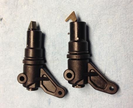
Here we have the two front knuckles put together, after some trial and error on the assembly. Here you can see the o-ring that I was talking about and the other pin holding the quick change assembly. When you mount and dismount the wheels you will want to pay attention to that exposed pin because if you lose it then the whole assembly will fall apart. On my truck it seemed to stay pretty tight but be careful!
Now I have assembled the front knuckles to the caster blocks and like a knuckle head I don’t have a picture of how you place the insert into the caster blocks so you will have to visualize this part. Where the hinge pin goes through the caster block you can change the insert which affects the angle of the caster on the truck. For example, the truck can have 0 degree caster block setting, two degree or four degree. Each of these is a tuning option for you to experiment with. Now here is the catch. How you insert that insert will affect not only your caster but also the front track width. If the hole in the insert is the farthest away from the quick release assembly it will make the front width wide. If the hole is closer to the quick release assembly it will narrow the front width. I built my truck in the wide configuration. Make sure you readjust your toe and camber when you change the insert from narrow to wide and wide to narrow.
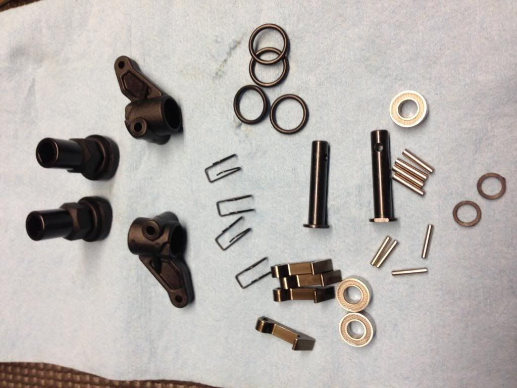
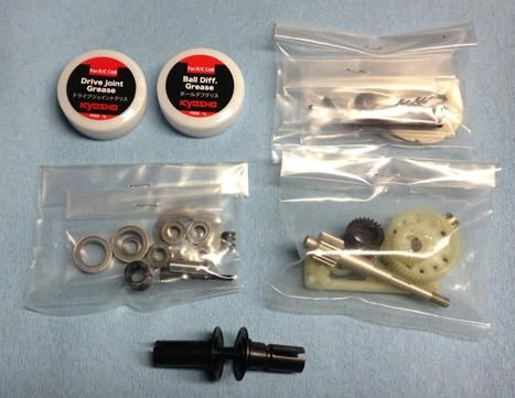
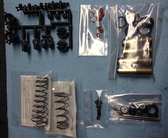
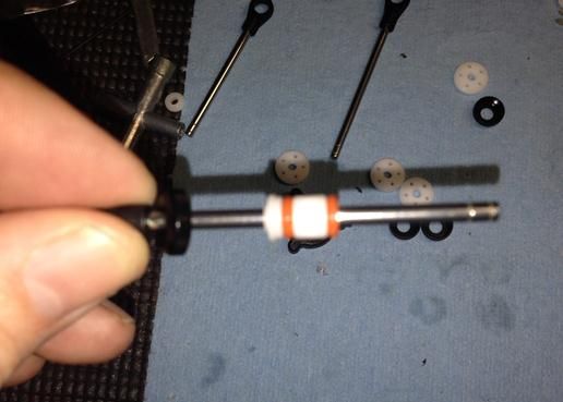
Next up is the differential assembly. It is very similar to the Associated differentials but the difference is in the quality of the materials being used as each manufacturer specs their own material. This bag includes everything you need to build the transmission for either the mid-motor or rear motor configuration. The manual walks you through each build configuration. I will be running my truck rear motor so those are the steps that I followed. What you see in the picture is everything that I need from the bag to build it.
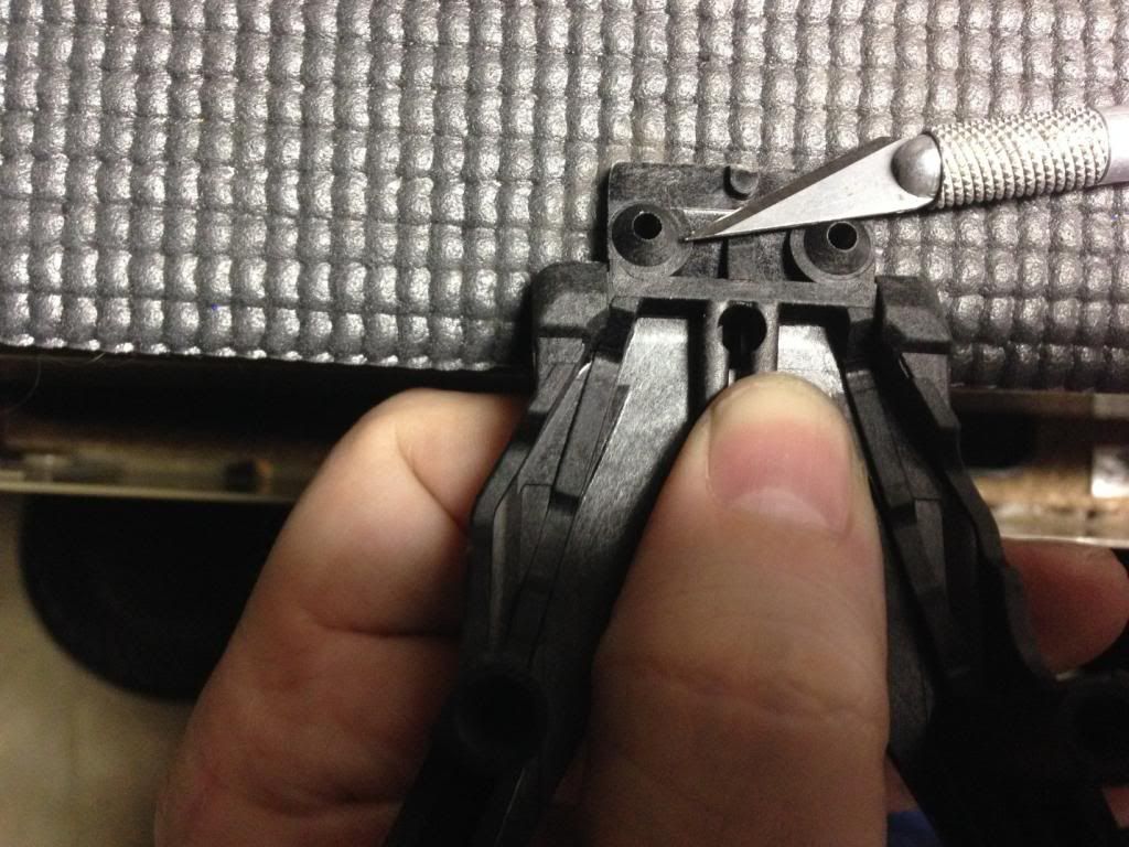
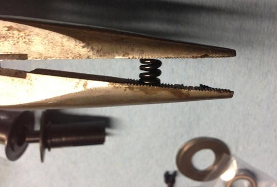
One of the tricks I have learned through the years is whenever you have a spring you will want to compress it a couple of times. Here I am using my needle nose pliers to accomplish this. This spring is the one that will go in the out drive of the differential. I will also do this to the one on the slipper but we are not at that point yet.
Another thing that I do is I sand the diff rings down to make sure they are as flat as I can possible make them. I know there are companies out there that offer this and are probably better than my work but I didn't have time to order them so I did it myself. I used 600 grit sand paper and a little diff ball grease to keep the ring attached to the out drive. I colored the diff ring with a sharpie so I knew when I hit that spot on the diff ring. I then put a little water on the sand paper and moved the out drive in a circular motion. In this picture you can see where the ring has made contact with the sand paper.
Here is one other thing to look for on the diff rings. Since I believe these are stamped from a big sheet of metal you will find a round edge and a squared off edge on the diff rings. I always make sure the rounded edge is facing the diff balls.
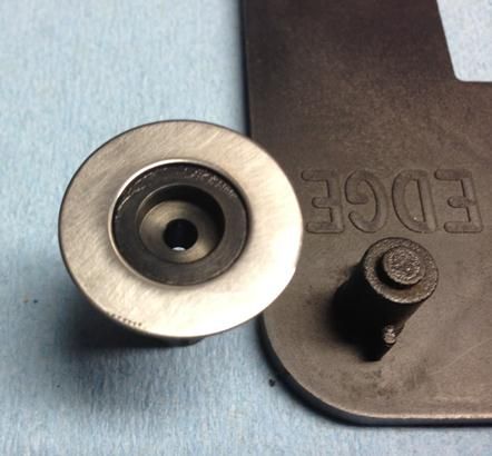
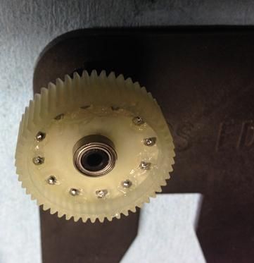
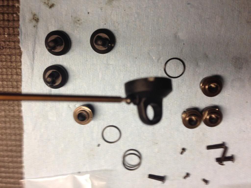
So I now have my diff rings wet sanded and ready to proceed. I am using my Racers Edge Diff tool to hold my out drive in place to assemble this. Now I have heard people say use a lot of grease on the balls and some say don’t use to much just enough to cover the balls. So this is what I have here, enough to cover the balls and a little extra to go around in case I missed a spot. If you use a lot chances are it will just fling off the differential gear and it will get on other gears in the transmission. While I don’t mind some messy things if I can limit or control how dirty something can get I will do my part to control it.
Next up is the thrust balls. You will use the darker colored grease to assemble this piece. Yes I wet sanded those washers too, you caught me. I install one washer on the diff bolt and then put some of the dark grease on it. I then take that to the area where I have laid out the thrust balls and pick them up using the grease. I don’t want to risk using my hands as these things are small and I am almost guaranteed to lose one doing it that way. Once I have all of the balls picked up I place the other washer on the diff bolt.
Now I am putting all of the pieces together. When you insert the diff bolt you will want to make sure that all of the thrust balls stay in place. Otherwise you will have trouble when you go to adjust your differential.
Here you can see the diff bolt coming through the nut and into the nylon portion. This is a good sign. Just make sure you do not tighten the diff bolt to tight as that can cause damage to the thrust washer, thrust balls, diff rings, diff balls and the plastic piece that holds the diff not. That plastic piece has two ears on it that fit in the slots in the out drive. If those get damaged then the plastic piece will just spin in the out drive and not tighten down. Then you will need to get a new one which comes with the diff gear.
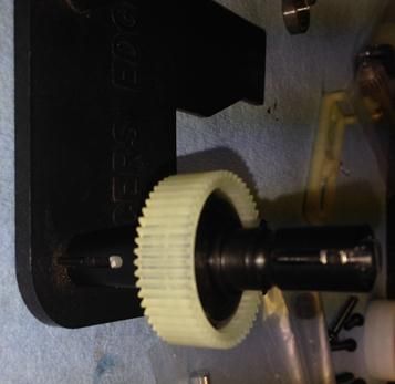
Here is a little tip with helping to break-in the differential. I take my drill and open up the chuck to the maximum size. I then insert one of the out drives into the chuck and slowly tighten it by hand. Once it is snug I will then hold on to the gear and slowly turn the drill on. The other diff out drive will turn in the other direction when I do this. I will do this for a couple of minutes on slow speed and then change the direction of the drill and repeat the process. While this doesn't completely break in the diff it gets you one step closer.
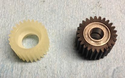
Inside the transmission bag you get a white/clear looking idler gear and a black gear. It has been found that the black gear provides a higher durability than the white/clear gear does. This is beneficial when running lower turn motors and on high traction surfaces. Now Kyosho has released an aluminum idler gear (UMW718) but that is more for the mid-motor configuration than the rear motor configuration. The reason being is you do not want to run metal on metal but in the mid-motor you have two idlers so you can go metal, plastic, metal, plastic. In rear motor you would have metal, metal, and plastic and things would wear out quickly.
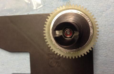
When you install the differential into the gear box make sure the diff bolt is on the passenger side of the truck, opposite the motor plate. I say this because there is a hole in the out drive that you can insert a small wrench/screw driver into it and use it to adjust your differential if needed. If it is on the motor plate side that hole is a little more difficult to get to.
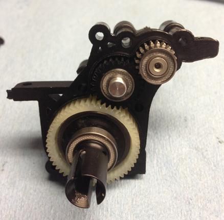
When you assemble the transmission together don’t forget to install the motor off-set spacer. This moves the motor mounting plate over to help position the center balancing point of the motor in the center line of the chassis. By doing so this makes it easier for you to balance the truck from left to right or right to left. Don’t forget to remove any extra flashing that might be on the gear case. In the pictures shown I have yet to do this.
Here is something to consider. Kyosho offers a Carbon Composite Gearbox for the RB6 which just so happens to share the same gearbox as the RT6, UMW504C. While I have used them in the past I didn't in this build and I am not sure why. I did find that this optional gearbox went together easier than the stock piece on my other vehicles and it was easier to get the transmission to spin easier once the screws were tightened down. However, mine was pretty free with the stock case here so that is probably one reason why I didn't swap it out.
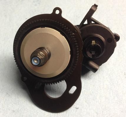
When you assemble the slipper assembly to the top shaft don’t forget to include the gold spacer, not shown. Don’t forget to make sure the slipper pad is properly seated in the spur gear when you put everything together. If it isn't the slipper will not work properly and you risk some damage to the slipper pad when you crank down on the nut.
So now we are going to star to assemble the rear suspension. In the kit you will notice plastic blocks fro the rear inner hinge pins but my pictures shows aluminum. Here is why this is. I have an RB6 and I purchased UMW706 and UMW705 since I was running rear motor. Since then I have switched that to a mid motor setup and I didn't need the UMW706. So I just purchased another UMW705 for this build.
One thing nice about these optional pieces is I can change the rear width of the truck and I can change the rear toe-in. To me it is a nice to have but it isn't a have to have because I never broke a plastic rear hanger on any of my vehicles, buggy to SC, but your experience may vary.
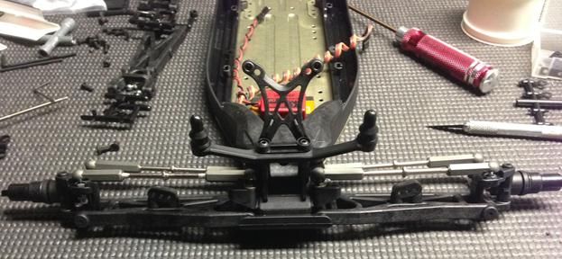
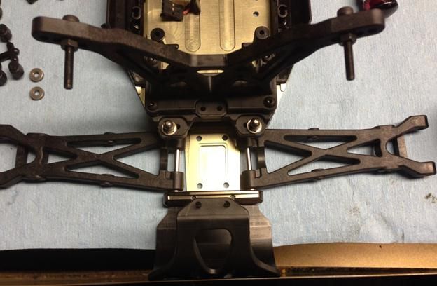
So now what you are looking at here is the assembly of the rear bulkhead along with the rear shock tower bolted to it. If I was building this as a mid-motor truck it would look a little different. One thing that you might want to think about doing, but not required, is to insert set screws in the remaining open holes were the ball stud goes in. What this does is it makes the plastic surrounding the ball stud stronger. Like I said it isn't required but it might help.
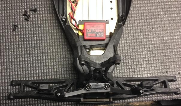
So now I have placed the rear suspension arms on the chassis and secured them with the rear suspension mount. The motor cover is keyed into the chassis just below this suspension mount and that is why it is on the truck at this time.
Don’t forget to ream the holes for the rear suspension hinge pins if you have a reamer.
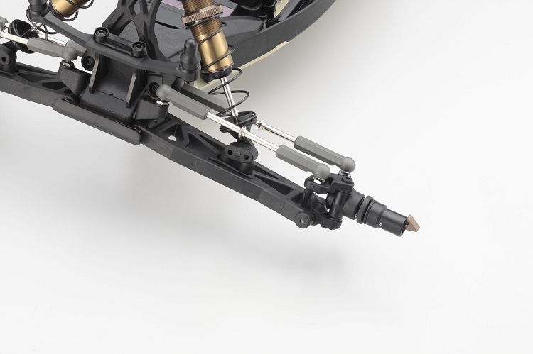
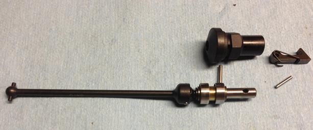
Up next is the rear axle assembly. If you got a little lost on the front assembly maybe this picture will help you out. I tried to show how they went together. So you obviously have the axle assembly with the bearings and the spacer that goes between them. Then you have the plastic piece with the hex on it and that first hole on the left when looking at the picture will accept the large pin.
So imagine this installed in the hub and you just inserted the outer bearing into it. After the bearing you will have a small spacer that is installed and then the plastic piece. Then you will want to align the holes in the plastic piece and the axle and then insert the pin. You will then want to slide the o-ring into place to prevent the pin from falling out.
Now you will take the quick release mechanism and attach the sprint to it as shown in the picture. Slide that into the plastic piece and line up the hole so you can insert the small pin. This small pin seems to stay in place because of the pressure the quick release assembly places on it. However, still keep that in mind when you remove the wheels from the truck as you don’t want to lose it, especially if you don’t have spares.
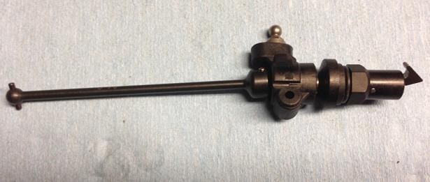
Here is the picture of the final assembly. Oh look at that, another hole to ream out with my 3.0mm reamer.

I have gone ahead and assembled the other axle in the hub and attached the rear camber link rods. One thing to mention about the camber links and steering tie-rods is that they all go on in a specific direction. This way when you take your wrench to make an adjustment when you turn the turnbuckle one way it will either shorten the link or make it longer. You want all of them setup the same way so you don’t give yourself a headache when trying to set them to the proper length. Please refer to the manual for additional information on how they wanted you to install them.
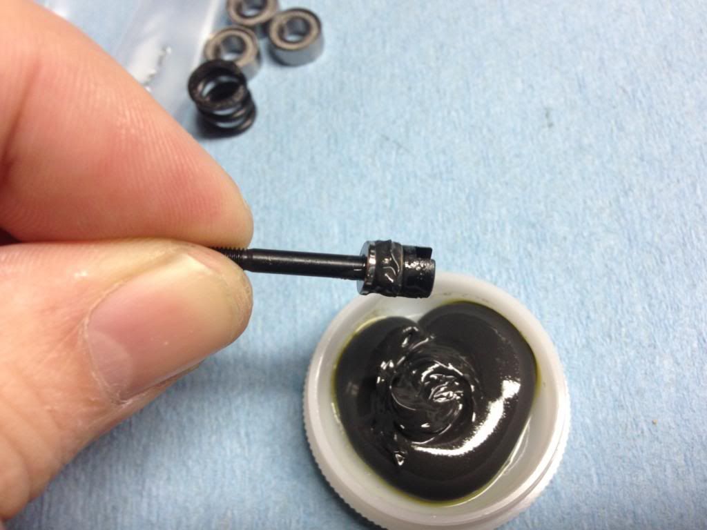
Ok, so now I have installed the rear hub into and connected the camber link so the dog-bone doesn't fall out of the out drive. Since we have metal and metal contact and it is pretty good force being applied here I recommend putting a small amount of black grease on the pins. This grease will help reduce the wear on the pins and increase the life expectancy on the pins and the diff out drives. It doesn't take much because you don’t want to put a lot on it and have it get flung off when you hit the throttle and have it get all over.
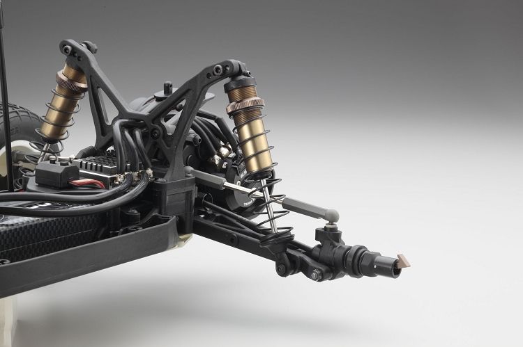
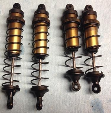
Now we are going to move on to the front and rear shocks. Kyosho has some of the best shocks for R/C as people will tell you. Once you have experienced them you will agree that they are some if not the best. Starting with the RB6 and continuing with the RT6 a set of X-Gear springs are included along with the 5 hole shock pistons.
A change in the kit from the buggy is the plastic shock tops. Now some will start to moan about this change and why did they do this? But for me, I would rather have the aluminum bell-cranks than the aluminum tops on my shocks. So to me this is a win situation in the swap out. But not everyone sees it this way but I understand your stance.
One thing that is different from the aluminum top is there is a screw in the top to bleed the shocks. You should only have to deal with this screw if you build the shocks in a different method than described in the manual. What that process is is a very good question. I imagine it is similar to Associated or Yokomo shocks but I haven’t looked at their build instructions in a long time so I could be wrong.
There is now an o-ring that goes into the top of the shock cap. This o-ring will keep the oil in the shock and not have it leak out the threads when the piston is compressed. Be careful to position the o-ring in the proper position otherwise it could be damaged when you assemble it to the shock body.
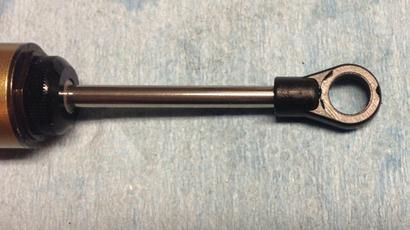
Up next is building the shock bottom. One thing that is not shown is the installation of the eyelets on the shock shaft itself. I will tell you this is I have cheated and used my drill again to install the eyelets. I chucked up the shaft in the drill between the e-clips, the area where the shock piston would ride so I didn't mark up the shaft. I then slowly spun the shaft in the drill and connected the eyelet. Make sure you go slow as you can go to fast and ruin the eyelet.
The kit includes the standard red o-rings but Kyosho offers some other o-rings as tuning options. They have the ORG03XR Grooved Low Friction O-ring and the ORG03X Grooved O-Ring. So how do you tell them apart? Well the XR is the same color as the stock ones but do not look like an inner-tube. The X looks like the same as the XR but it is clear in color. I believe the X offers less stiction (grip on the shock shaft) than the XR. The XR has less sticktion than the stock o-rings. What is sticktion? Well to me it means how tight the o-ring is on the shock shaft. The tighter fit to the shaft the more force it is going to take to move that shaft in and out of the shock. Honestly, I don't know if sticktion is a real word because my spell check doesn't like it.

On the shock shaft I placed a small amount of oil were the e-clips would go so the o-ring would not snag or get caught on the edge of the groove. I then followed the assembly steps as shown in the picture. Just remember to be careful when working with the o-rings. When putting this assembly together with the rest of the shock cartridge be sure to use plenty of oil during assembly.
When I was assembling the piston in between the e-clips I noticed a small amount of up and down play between the e-clips. What I found is, just like the diff rings being stamped, the e-clips appear to be stamped too. They have a smooth or rounded edge and a not so smooth edge. By taking the not so smooth edge of the e-clip I was able to install it so that side was facing the piston. This took up the space or gap that I noticed between the shock piston and the e-clip and it didn't move up and down anymore. Sorry, I thought I had a picture but I don't.
Now with the shocks built using the steps in this video, click
here, you have to install the shock balls into the eyelets. As you look at the different sides of the eyelets you will notice one side is flatter than the other. It is this flat side that you will want to insert the ball into. If you have a question about which side is which take a look at the picture as you will see a mold line on the flat side as shown above.
I have now installed the shock bushings and lower pivot balls into the eylets of the shocks, installed the springs, lower colors and the adjustment nuts to set ride height. All that is left is to install them on the truck.
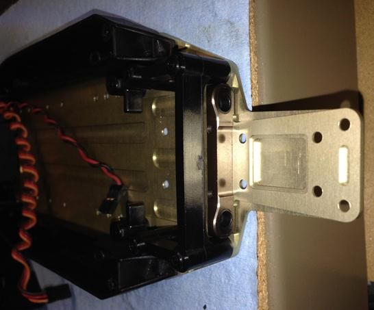
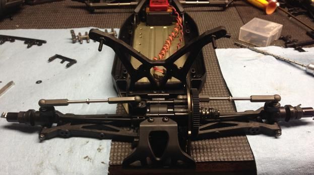
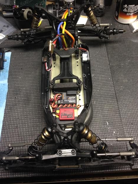
With the socks installed on the truck and the electronics installed in a whimsicle manor I just need to add the body and tires and be all set to go. The truck, as it is pictured, is setup to run a shorty pack in it. By running this type of pack I can place my receiver in front of the battery and keep the speed control behind it. During the build, the manual talks about a shelf for the rear but I left that out. I felt it was better to stick the speed control to the chassis rather than this shelf.
Once I get to the track I will give the final adjustment to the slipper and after the first run I will check the tightness of my differential. One thing that I do is tighten the slipper nut all the way so the spring is compressed. Then I will give a couple of blips of the throttle to hear if the diff is loose. If it makes any type of noise I will tighten it up. If it doesn’t then I know it is tight for that initial run and I will loosen the slipper nut and set that accordingly. This does put a strain on the slipper spring but for the short amount of time I am doing this to check the slipper it shouldn’t hurt it. There are other ways to check the tighteness of your diff but check with your local track veterans to see how they set theirs. This way you can do it the same as them and if there are any questions you can inform them the steps you performed and they will be able to relate.
If you have any build tips or see any errors that I made let me know and I will correct them. As always, if you have any questions post them here and we will do our best to answer them.
Thanks for reading!
--------------------------------------------------------------
As seen in this post by Derek Furutani, click
here.
Derek Furutani found an old body that will fit Mid motor. It is a gas truck body for the Ultima ST.
It may not be a modern cab forward body, but it fits with no issues.
The part number is RS35 for the body and the decals are RS140.
You can find it by typing the part number into the search box at Kyosho America.
