I've been playing with my own transponder design, and thought a few of you might be interested in learning about it. Here's a picture of the second breadboard, constructed to try out the PC layout (the connections are located in the same places as they would be on the PC layout). It is through-hole rather than surface-mount, so it is easier for me to construct:
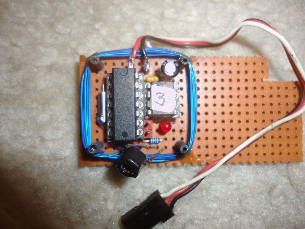
I have not made any PC boards yet, as it's still too early in the design process (and I'm too cheap to spend the money, at least right now).
I have tested the prototypes on the AMB system at my local track to prove the concept. The transponders use a 5MHz carrier frequency and Binary Phase Shift Keying (BPSK), with the bit spacing at one per four carrier cycles.
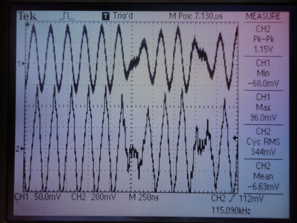
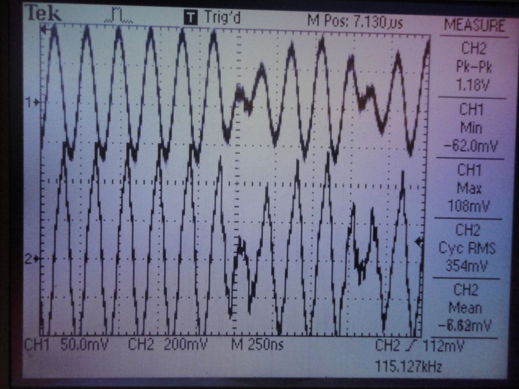
To illustrate the modulation scheme, here's a scope shot of the output from an AMB transponder, using a single-turn loop pickup fed into my oscilloscope. The bottom trace is a loop directly over the transponder, and the top trace is a loop a small distance away with a -6db per octave RC filter.
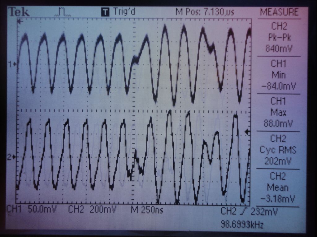
As you see, the tuning and Q of the output tank (coil) within the transponder rings a bit, so there is a small, extra blip in the waveform where the phase is inverted in the modulating waveform.
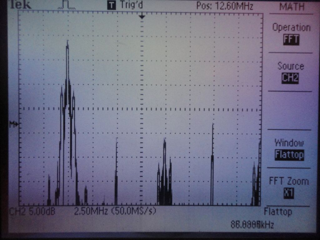
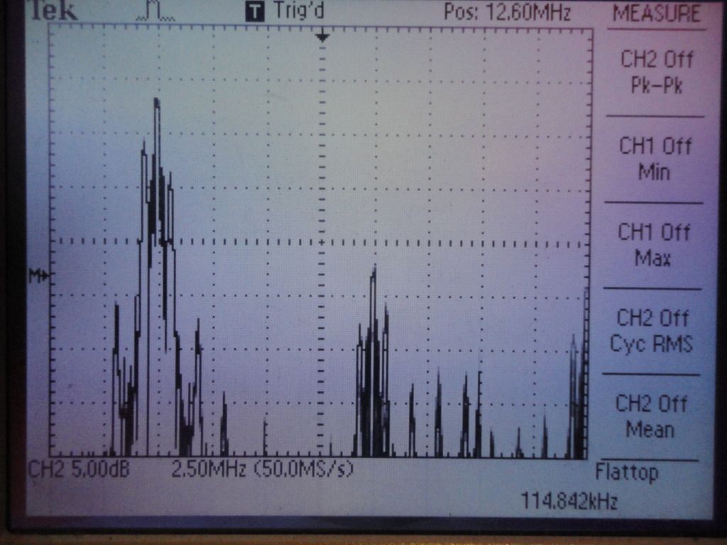
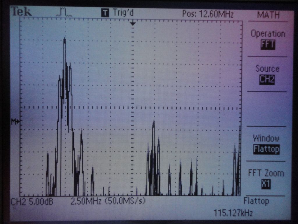
The spectrum of the output is also interesting:
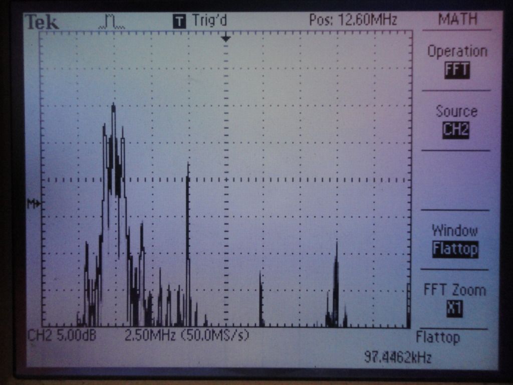
You can see that the Upper Side Band (USB) and Lower Side Band (LSB) are about the same amplitude, which means that the output tank is tuned nominally at the carrier frequency. Also interesting is the rather large second harmonic spike at 10 MHz, indicating that the drive to the tank circuit is asymmetrical. Although this is probably of no significance in the operation of the unit, it can make it more difficult to meet FCC emissions regulations.
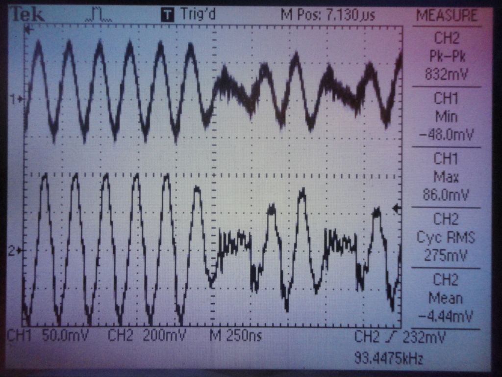
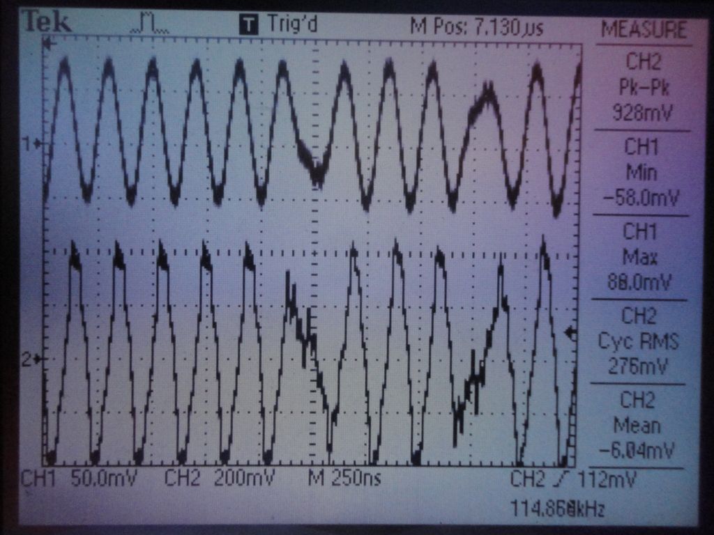
An MRT transponder shows a similar output waveform, although the slightly different tank drive, tuning, and Q has eliminated the extra blip where the phase inverts:
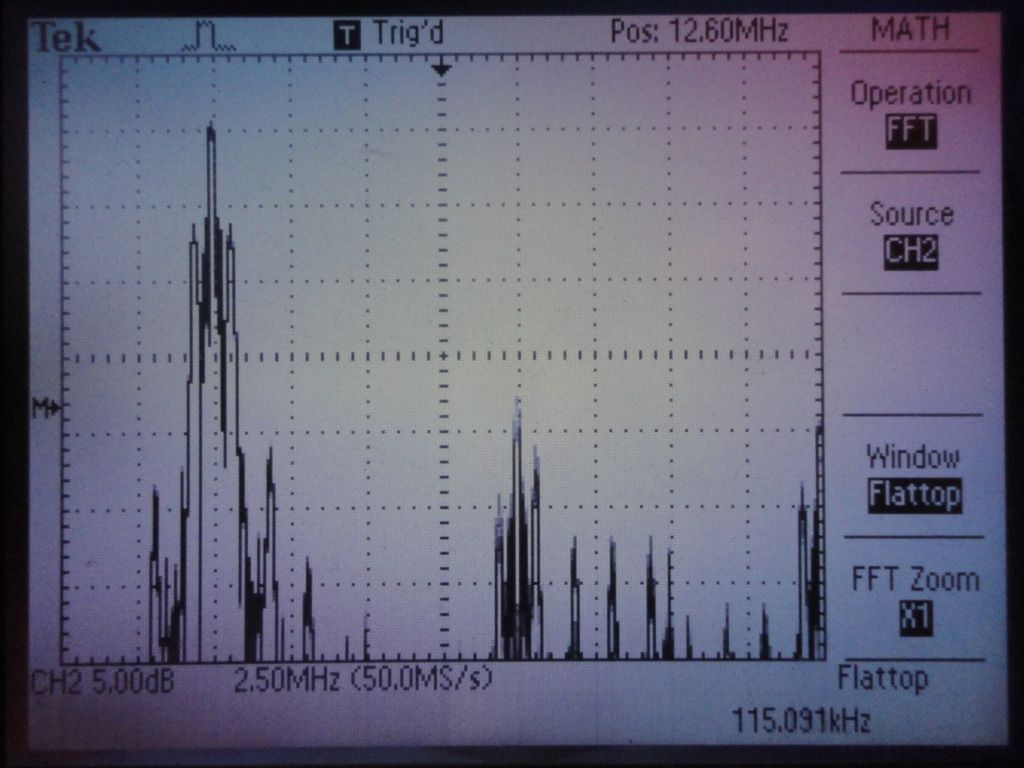
The MRT spectrum has less harmonic content than the AMB, most likely due to a higher tank circuit Q:
The LSB is a bit greater than the USB, so the tank circuit is tuned somewhat below the carrier frequency. (Other transponders I have show tuning both above and below the carrier frequency, so it doesn't appear to be critical to operation.) Both sidebands are much lower in amplitude than the AMB, due to higher tank Q. The effect of the higher Q can also be seen in the MRT waveform, which takes longer to ring up after a phase inversion.
Finally, here are three sets of scope shots from my breadboard transponder. The first set is with the tank tuned at the carrier frequency:
This set is with the tank tuned below the carrier frequency. You can see how this pretty much eliminates any extra blip when the phase inverts:
Finally, a set with the tank tuned above the carrier frequency. This accentuates the extra blip:
One obvious thing about my design is that the spectrum shows virtually no second harmonic spike, because I drive the tank symmetrically. While this is not necessary for operation, it does make it easier to meet FCC requirements, and appeals to me aesthetically.
I am starting on a decoder design. The first try will use a PLL to detect the phase inversions from modulation. If I use simple zero-crossing information to feed the PLL, the output should indicate a phase change on either of two conditions: an increase in frequency due to the extra blip present in the output waveform of some transponders, and a decrease in frequency from those transponders not having the blip. This sounds pretty simple to do.