I worked on the battery tray design in Solidworks today..that will allow me to mount the battery over the belt.. the secret is the battery. The post made by mos_leung gave me the idea of using the Yokomo 2800mah 7.4 battery. Which is about the same size as a 1s lipo.. so its only 18.5mm tall.
The only draw back to the battery is the low capacity.. fortunately, I will only be running this car in 17.5 blinky and 17.5 open. I'm pretty sure 2800mah will be enough for these classes.. if someone were to drive this in modified.. it most likely wouldn't have enough capacity.. yet, this car is designed for the future , and I believe that battery technology would eventually catch up and I'm sure a battery the same size as the Yokomo but a higher capacity will eventually come out. At this time... this car wouldn't be produced because the design of the car isn't ROAR approved. But in the future... possibly.

The battery weighs 146g compared to a shorty lipo at 213g. In order to raise the battery up over the belt and make up the weight.. I had to design a battery tray. It is 93.5mm x 46mm and is only 18.5mm tall. With pretty much all of the new shorty lipo's are 25mm tall.. this gives me 6.5mm for the battery tray.
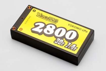
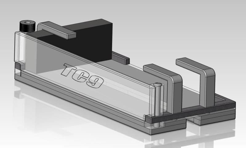
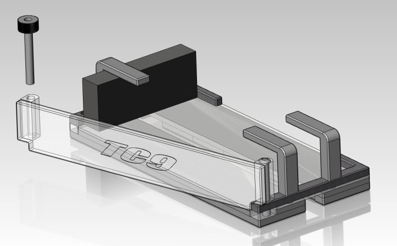
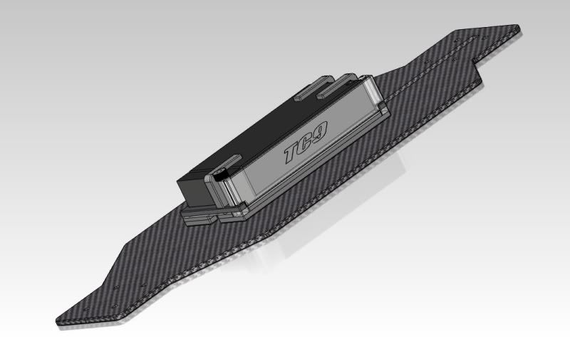
Here are some CAD images of my battery tray design.. it is side loading.. to get the battery out all you have to do is unscrew the thumb screw with a threaded rod on in..and pulled it out, open the battery door and sliding the battery out. This makes it so I don't have to bottom load the battery like the E4 and the Jrx-s

The tray will be secured to the chassis by four screws..separating the chassis and the tray will be four o-rings.. I'm hoping that this will allow the chassis to flex. So the tray will actually be "floating" about 1mm above the chassis. Additionally, the third layer of the tray that connects the two sides..of the tray will be 1mm lexan.. this will also help the chassis to flex as it should.
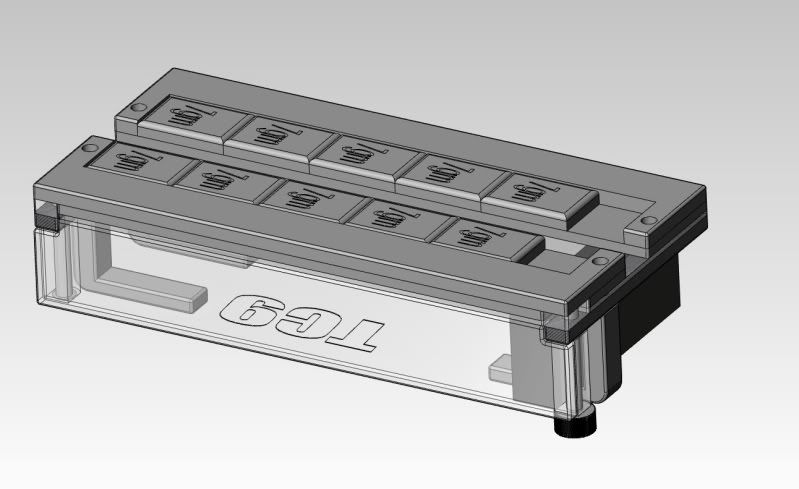
On the bottom of the tray are slots for lead weights.. you can slide the weights forward and backward in order to get perfect 50/50 weight. Also, you can slide the battery forward and backward. A foam spacer fills the extra space.
The first layer on the tray will be made out of 3mm aluminum , the second layer will be made out of 2mm aluminum, the third layer out of 1mm lexan, the battery braces 3mm carbon, and the battery braces which go over the battery will be 6mm lexan.
The belt will run under the tray in the channel. The channel allows 6mm of clearance for the belt.
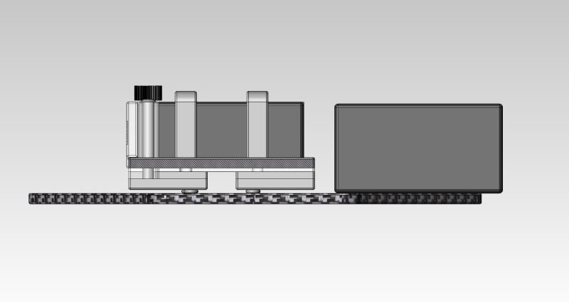
Here is a picture comparing the height of a shorty lipo compared to the Yokomo battery in my tray.. The top of the Yokomo battery in the tray will be at 25.5mm..only .5mm higher than a normal stick battery
Originally Posted by
valk
i dont have a tc6 so this might be a dumb question, but why did you have to double up the diff pullies like that? couldn't you have just placed the difs both on the same side? belt would be slightly offcenter but is that really that big a deal? also curious how your gonna mount the battery low with the belt arranged like that. kinda defeats the purpose of moving your motor to center if the battery is still sitting outboard to clear the belt.
even with a stubby lipo would have to add a lot of weight on the other side to balance with the battery. electronics wont be even close.
average brushless motor = 170gr average 7.4v hard lipo 280gr.
I have a couple reasons for doubling up on the diff pully's in order to move the belt to the center. The first reason is that I can switch between running two belts and a single belt with two diff pulleys..allowing me to experiment and tune the drive-train depending on the traction level and power of the motor. Since I have two pully's in the rear I could run one belt from the drive pulley to diff pulley closest to the bulkhead..and then run another belt on the center diff pulley to the front center pulley. The second reason is that if the belt was offset then the channel in the battery tray shown above would also have to be offset..which would then cause the battery tray to be unbalanced. The battery will be placed in the exact center of the chassis.
Originally Posted by
Xpress
I don't know if this will come into play or not, but I think one of the reasons the xxxs drivetrain worked was because the tensioner pulley was used on the "slack" side of the belt. Under load the drive pulley pulled the belt tight between it and the rr diff pulley and then the front diff pulley. All of the wrap around the tensioner was never high load.
With your current design the drive pulley is putting drive tension into the belt as it snakes its way around the tensioner.
Does this make any sense?
I like the way you have run the belt around the motor, but perhaps the layshaft would be better in front of the motor?
Hmm.. I do understand what your saying..and it does look like the belt would be putting force on the idler as the car accelerates.. I too am not sure if this would come in play.. we will just have to see. Unfortunately, the drive pulley has to be in back of the motor for the layout to have good front/rear distribution... so if I can't seem to a get the one-belt system to work.. I can just switch to a two-belt system.
Originally Posted by
daleburr
Stubby Lipo = 200g
Servo = 50g
ESC = 80g (with wires)
Receiver = 10g
Transponder = 5g
TOTAL = 145g
So it's not that far off, especially as the car is likely to be light and require lead to get it upto any sort of minimum weight, so this can be put on the electronics side.
Since the battery is going to be dead in the middle of the chassis.. the weight will be divided like this..(the battery weight will cancel out left/right)
Right:
Esc: 55g (with wires)
Total = 55g
Left
Servo: 44.5g
Receiver: 3.1g
Total= 47.6g