


Corona 2.4GHz diy kit - convert old radios to 2.4GHz
 12-07-2009, 05:21 AM
#1

Couldn't find anything on here about this kit, was so cheap I thought I might as well give it a go, and it works great.
http://www.hobbyking.com/hobbyking/s...idProduct=9770
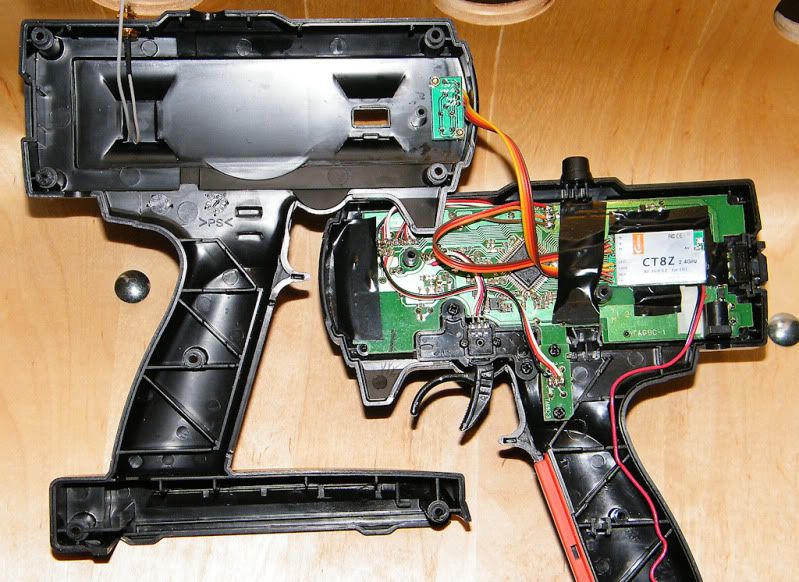
So far i've converted my Futaba 2PL AM 27MHz to be dual 27MHz and 2.4GHz. Futaba have made this one really easy. The same 3 wires that go from the main board to the RF board just go to the 2.4GHz module instead. Black = -, white = +, red = ppm signal (the connections are marked on both futaba circuit boards)
Would've been easier if I just took out the 27MHz board but wanted to be able to switch back if needed. So I wired in both and put a switch on the + wire.
Bought a couple of extra 4 channel receivers which is what i'm using at the moment, they're really small. The 8 channel will fit in any 2WD buggy too.
Drove the car off into the distance until I could barely see it and never lost contact so the range is fine.
Attached some pics of the install..
If anyone else converted their radios would be cool to post some details to help out anyone else with the same radios in the future.
http://www.hobbyking.com/hobbyking/s...idProduct=9770
So far i've converted my Futaba 2PL AM 27MHz to be dual 27MHz and 2.4GHz. Futaba have made this one really easy. The same 3 wires that go from the main board to the RF board just go to the 2.4GHz module instead. Black = -, white = +, red = ppm signal (the connections are marked on both futaba circuit boards)
Would've been easier if I just took out the 27MHz board but wanted to be able to switch back if needed. So I wired in both and put a switch on the + wire.
Bought a couple of extra 4 channel receivers which is what i'm using at the moment, they're really small. The 8 channel will fit in any 2WD buggy too.
Drove the car off into the distance until I could barely see it and never lost contact so the range is fine.
Attached some pics of the install..
If anyone else converted their radios would be cool to post some details to help out anyone else with the same radios in the future.
 12-07-2009, 05:55 AM
#2
Wow thanks for posting this!! This is a must buy for me.

12-07-2009, 06:03 AM
#3
The receivers are very inexpensive...hmmmm
My Helios might get a upgrade..
Anybody else try this out?????
My Helios might get a upgrade..
Anybody else try this out?????
12-07-2009, 10:53 AM
#4
It's a nifty looking product for sure, the one worrying point I would have is the latency figure. It's listing 22ms, which isn't a terrible figure, but even the original spektrum system came in at 5.6ms, which is 4x quicker to respond... My perspecitve is as a racer and a former FPS player where latency kills 
12-07-2009, 06:12 PM
#5
Yeah 4x of bugger all is still bugger all
I'm an FPS player too, usually get a 5ms ping but don't really notice increases even if it gets up to 50ms.
Felt the same on the track as the old 27MHz system anyway minus the glitches when someone turns on their transmitter with the same frequency!
I ran it sunday in the biggest race meeting of the year, so there would've been a few transmitters on in the pits at the same time along with 2.4GHz wireless ethernet going, had no issues.
12-10-2009, 06:30 PM
#6
I used the same Corona CT8Z kit as Bugle to convert a JR XS3.
Tricky part #1 - Locating the PPM signal
The XS3's synthesised system is located on a separate PCB and is connected to the main PCB via 9 wires. One of those wires is the servo signal (PPM). To determine which one, I hooked it up to an Oscilloscope and probed each wire.
The contacts to connect for the XS3 are the wires on the right hand side of the synthesised crystal PCB:
Wire 7 (red): Positive
Wire 8 (white): PPM
Wire 9 (white): Ground
If you don't have an oscillopscope, you can download software which uses the line-in of your sound card to trace signals.
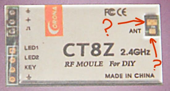
Tricky part #2 - Soldering the aerial
The 2.4ghz aerial needs to be soldered to the PCB. There are two points and they are absolutely tiny. You need some steady hands and a small, low wattage soldering iron. In the end, I asked an electronics friend to help me out.
Installation
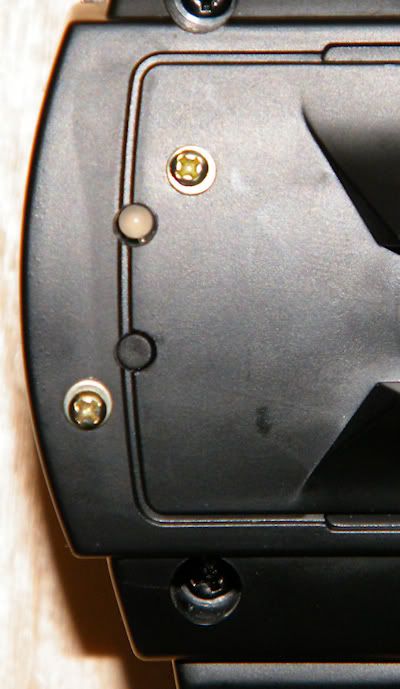
Other than that, installation is straight forward. Drill a few holes in the case, solder a few wires and your done. I also added a switch on the positive line to toggle between the original 40mhz system and the new 2.4ghz.
I've only had the chance to do some premlinary testing so will have more to report over the weekend. Curious to see how good the range is.
$35 for the kit and additional receivers are $20. Pretty good bang for your buck if you have multiple cars and looking for a way to move to 2.4ghz.
Tricky part #1 - Locating the PPM signal
The XS3's synthesised system is located on a separate PCB and is connected to the main PCB via 9 wires. One of those wires is the servo signal (PPM). To determine which one, I hooked it up to an Oscilloscope and probed each wire.
The contacts to connect for the XS3 are the wires on the right hand side of the synthesised crystal PCB:
Wire 7 (red): Positive
Wire 8 (white): PPM
Wire 9 (white): Ground
If you don't have an oscillopscope, you can download software which uses the line-in of your sound card to trace signals.
Tricky part #2 - Soldering the aerial
The 2.4ghz aerial needs to be soldered to the PCB. There are two points and they are absolutely tiny. You need some steady hands and a small, low wattage soldering iron. In the end, I asked an electronics friend to help me out.
Installation
Other than that, installation is straight forward. Drill a few holes in the case, solder a few wires and your done. I also added a switch on the positive line to toggle between the original 40mhz system and the new 2.4ghz.
I've only had the chance to do some premlinary testing so will have more to report over the weekend. Curious to see how good the range is.
$35 for the kit and additional receivers are $20. Pretty good bang for your buck if you have multiple cars and looking for a way to move to 2.4ghz.
12-18-2009, 12:41 AM
#7
Turns out the 22ms latency is just the length of a standard PPM frame, so there's nothing you can do about it, but it's exactly the same latency as what the radio originally started with.
Anyway i've converted another radio, this time a Futaba T2PHKA. Everything is contained on the one circuit board and it uses a Futaba FP-2108T chip used in many Futaba transmitters. It has a PPM output on pin 17 and Futaba were nice enough to put a pad on the circuit board for soldering a wire to. It's a bare copper pad between the IC and the crystal easy to find.
Just located the most convenient ground and +12v spots to power the module and it's done..
Where I stuck the module to the board there's a large ground area so it was flat enough to put double sided tape on.
Last edited by Bugle; 12-18-2009 at 12:56 AM.
12-18-2009, 09:34 AM
#8
That is awesome you DA MAN!!! I just ordered the kit from HC plus an extra 4ch Rx, will post results when I get receive them and install it on a 2PL.
12-20-2009, 01:38 PM
#10
Finally managed to get to the track to try it out and encountered no problems in regards to quality of signal. While on the drivers stand, I did a quick test drive to 80m away with no loss of signal. Would have gone further but couldn't see the car.
The only real quirk is the binding between the xmitter and receiver during power up. There's about a 5-10 second delay between power up and binding. Sometimes it doesn't bind on the first go - I then have to turn it all off and try again. On the second round, it always works
On the receivers, you have two antennas to deal with (primarily to improve signal quality for r/c aircraft). I don't think their arrangement is as critical in a car.
While I can't speak for R/C aircraft, it appears to be an excellent system for cars.
12-20-2009, 04:18 PM
#11
http://www.corona-rc.com/coProductE....assName=2.4GHz
Looking at the specs of the different Rx, the range seems to be very good.
Looking at the specs of the different Rx, the range seems to be very good.
12-29-2009, 02:13 AM
#12
Installed it in my 2PL Tx today. I used some electrical tape to cover the exposed solder points on the Futaba PCB as a safety measure against shorting. I mounted the LED/binding switch board on the far end of the Tx case. I will do a range test tomorrow.
Last edited by PaPeRo; 12-29-2009 at 06:32 AM.
12-29-2009, 05:11 AM
#13
"Upgrade your FM/PPM radio to the new 2.4Ghz DSSS technology with a Corona DIY system."
12-30-2009, 01:07 AM
#15
Does anyone know if you're supposed to solder the aerial to BOTH points on the PCB or just the smaller one with the "ANT" label? When I soldered mine I didn't solder the antenna to both pads, only the one with the label. Is the other pad connected to anything on the PCB or is it just there for a more secure solder area for you to use?
Anyway I did a simple range test today and it goes far enough for me, any farther and I'd have to use a pair of binoculars.
Anyway I did a simple range test today and it goes far enough for me, any farther and I'd have to use a pair of binoculars.
Last edited by PaPeRo; 12-30-2009 at 01:21 AM.