


 141Likes
Icharger x6 Mini 30A Discharge
 02-04-2020, 07:45 PM
#331
What are the cell voltages when it drops from 30a to 4a?
 02-05-2020, 05:47 AM
#332
Tech Initiate
iTrader: (2)
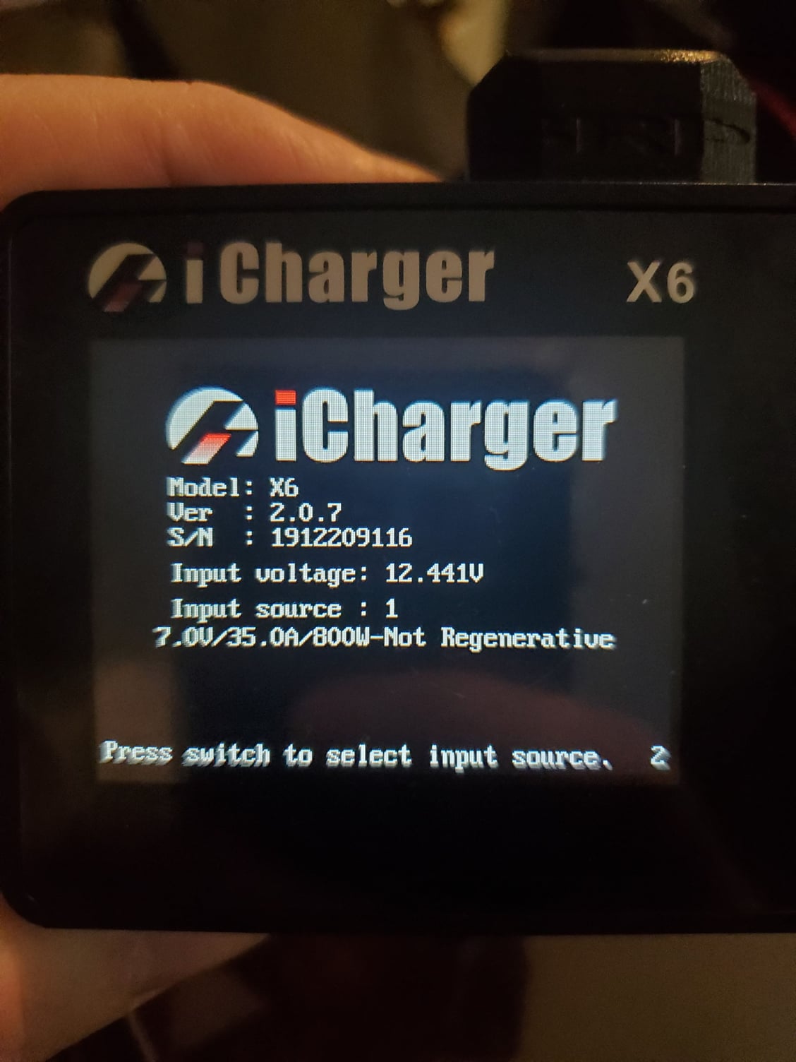
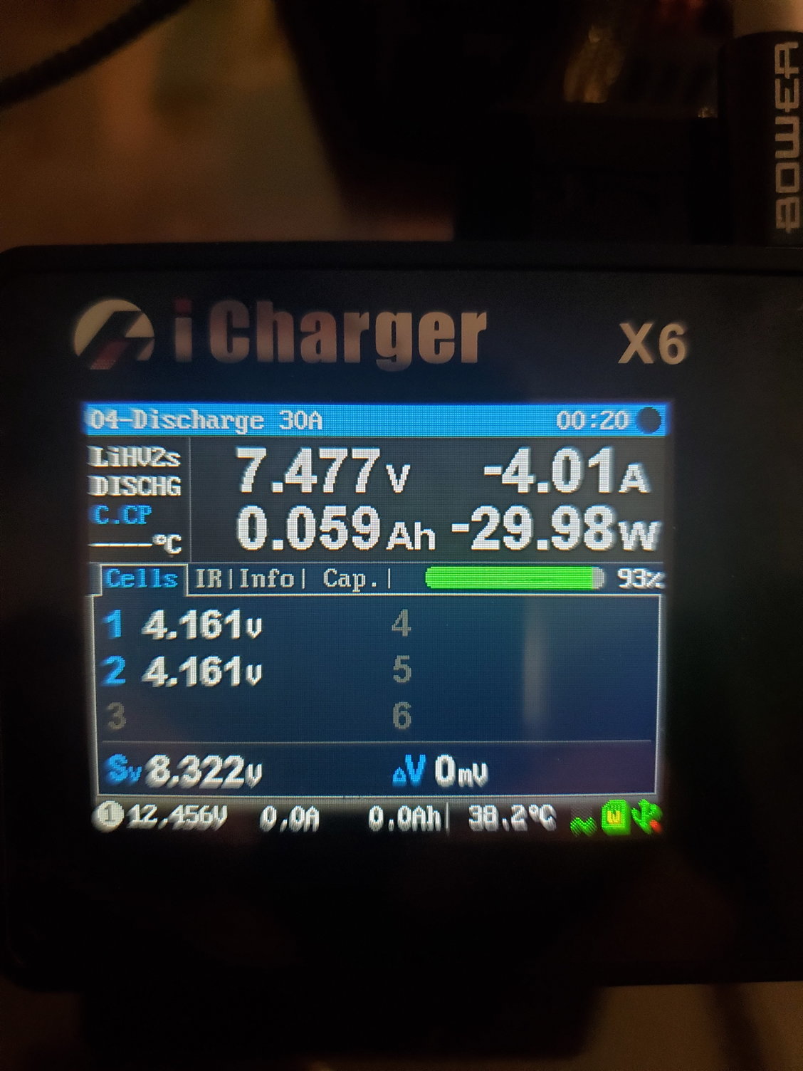
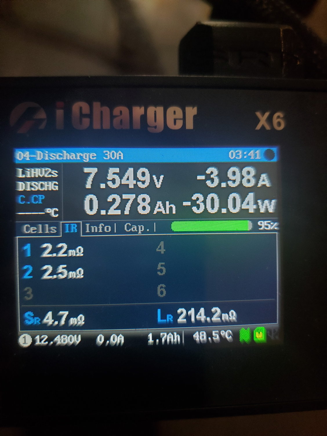
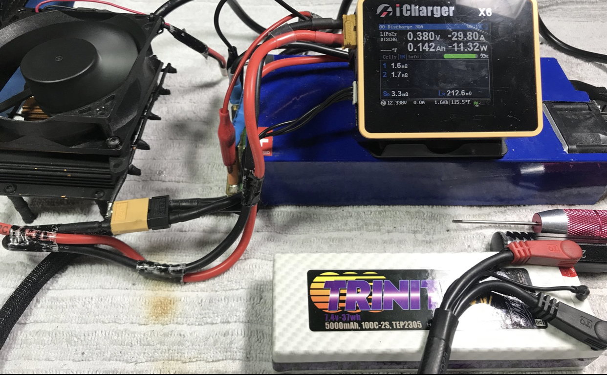
Data 4 seconds into the discharge cycle:
Top of the screen 1.879V, -30.57A, 0.010Ah, -57.44W
Cell 1 Voltage= 4.220V, Cell 2 Voltage = 4.213V
Sv = 8.433V
Data 13 seconds into the discharge cycle:
Top of the screen 7.666V, -3.91A, 0.051Ah, -29.97W
Cell 1 Voltage = 4.266V, Cell 2 Voltage = 4.263V
Sv = 8.529V
Top of the screen 1.879V, -30.57A, 0.010Ah, -57.44W
Cell 1 Voltage= 4.220V, Cell 2 Voltage = 4.213V
Sv = 8.433V
Data 13 seconds into the discharge cycle:
Top of the screen 7.666V, -3.91A, 0.051Ah, -29.97W
Cell 1 Voltage = 4.266V, Cell 2 Voltage = 4.263V
Sv = 8.529V
 02-06-2020, 10:04 AM
#335
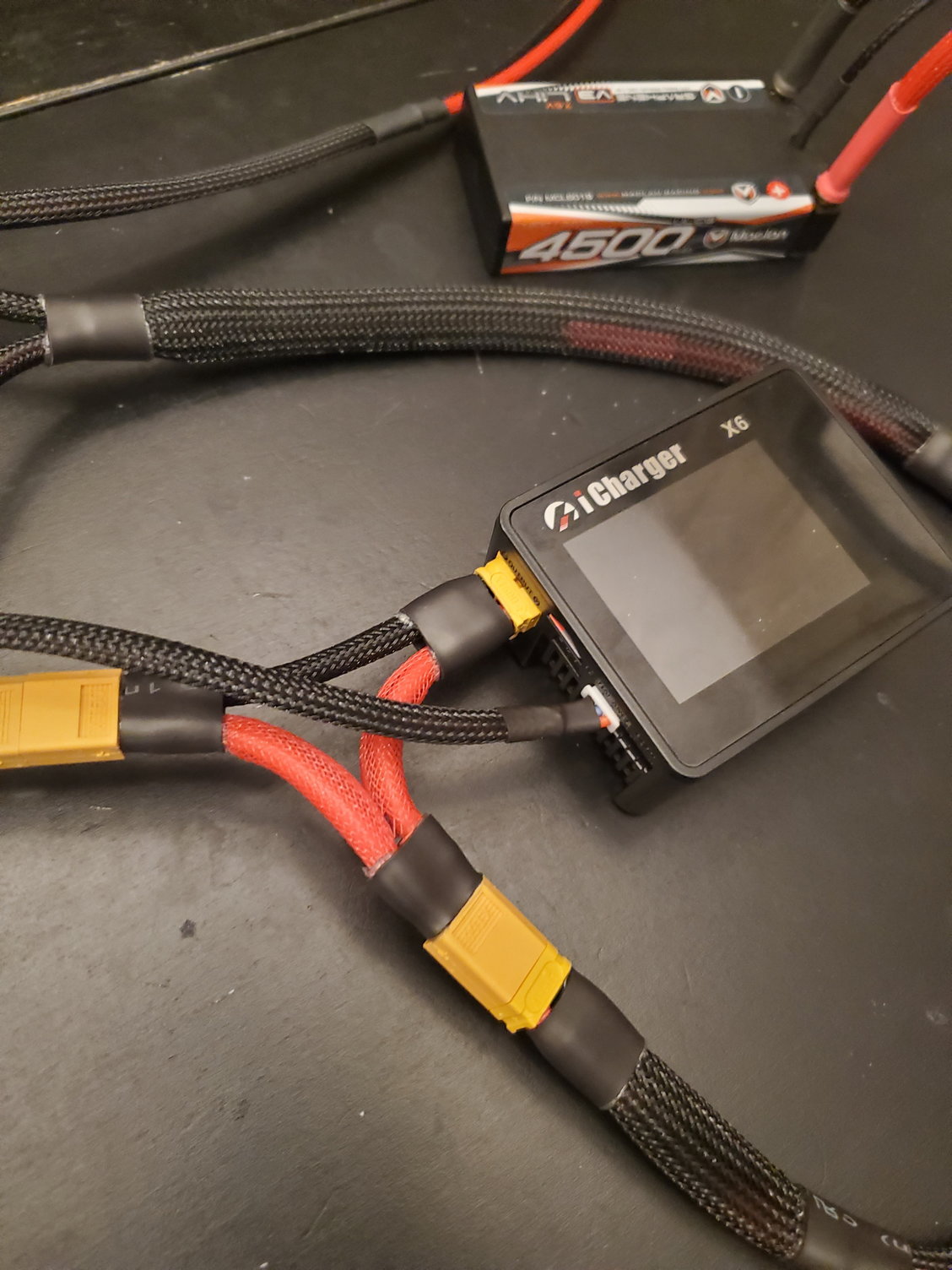
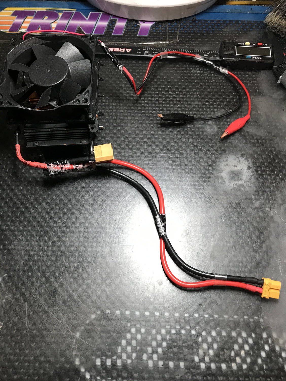
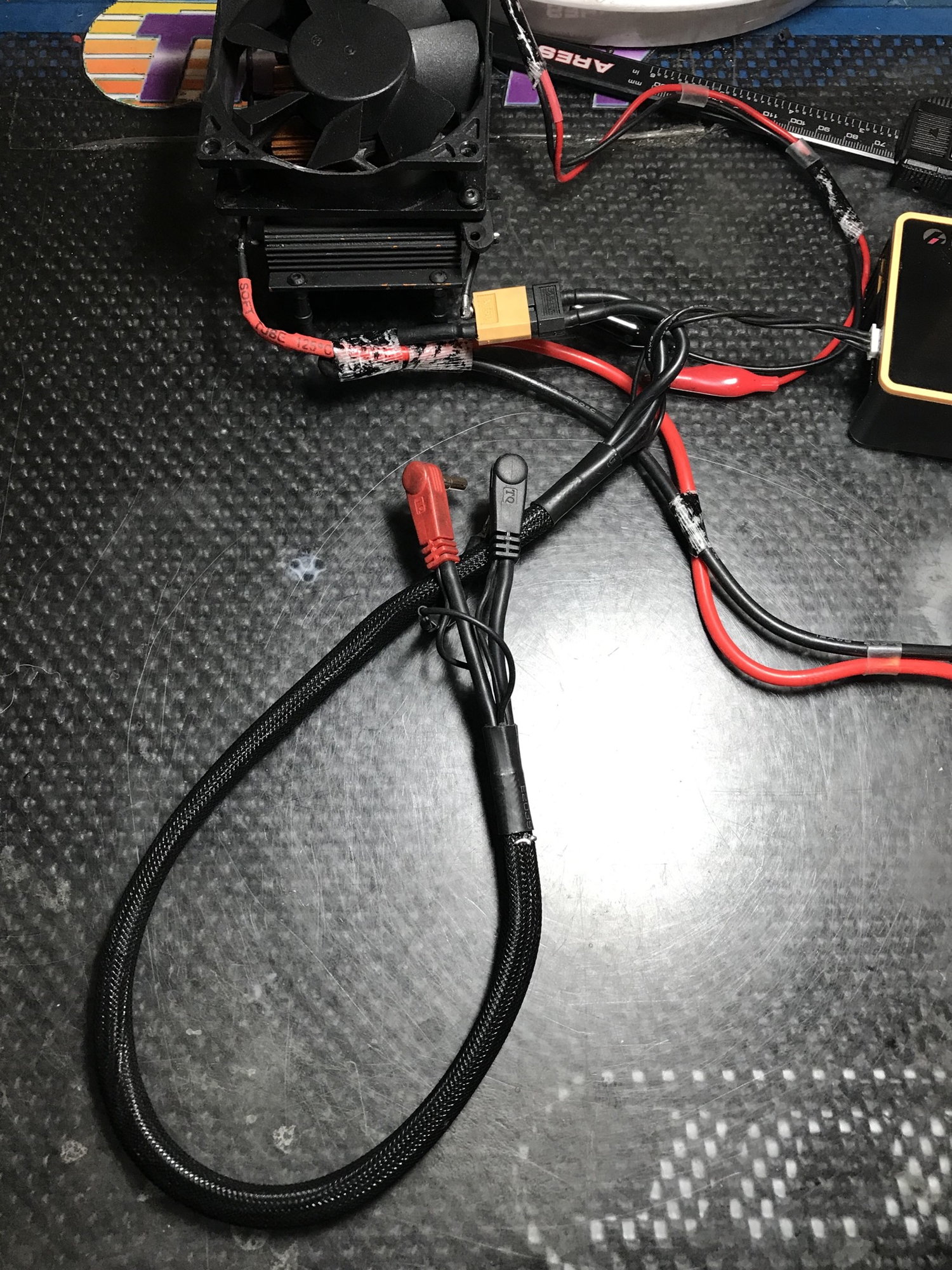
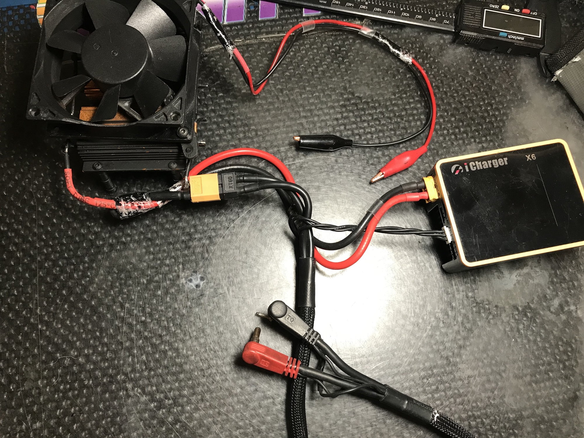
Thanks for the pictures The only thing I can't quite tell from the photo is whether your charge leads do have balance leads connected directly to the the positive and negative terminals of the battery. Is there a thin balance lead running along each main charge lead to the battery?
Could you show what the IR page is showing for each cell while discharging?
Could you show what the IR page is showing for each cell while discharging?
02-06-2020, 03:15 PM
#336
Tech Initiate
iTrader: (2)
Thanks for the pictures The only thing I can't quite tell from the photo is whether your charge leads do have balance leads connected directly to the the positive and negative terminals of the battery. Is there a thin balance lead running along each main charge lead to the battery?
Could you show what the IR page is showing for each cell while discharging?
Could you show what the IR page is showing for each cell while discharging?
 02-09-2020, 09:21 AM
#337

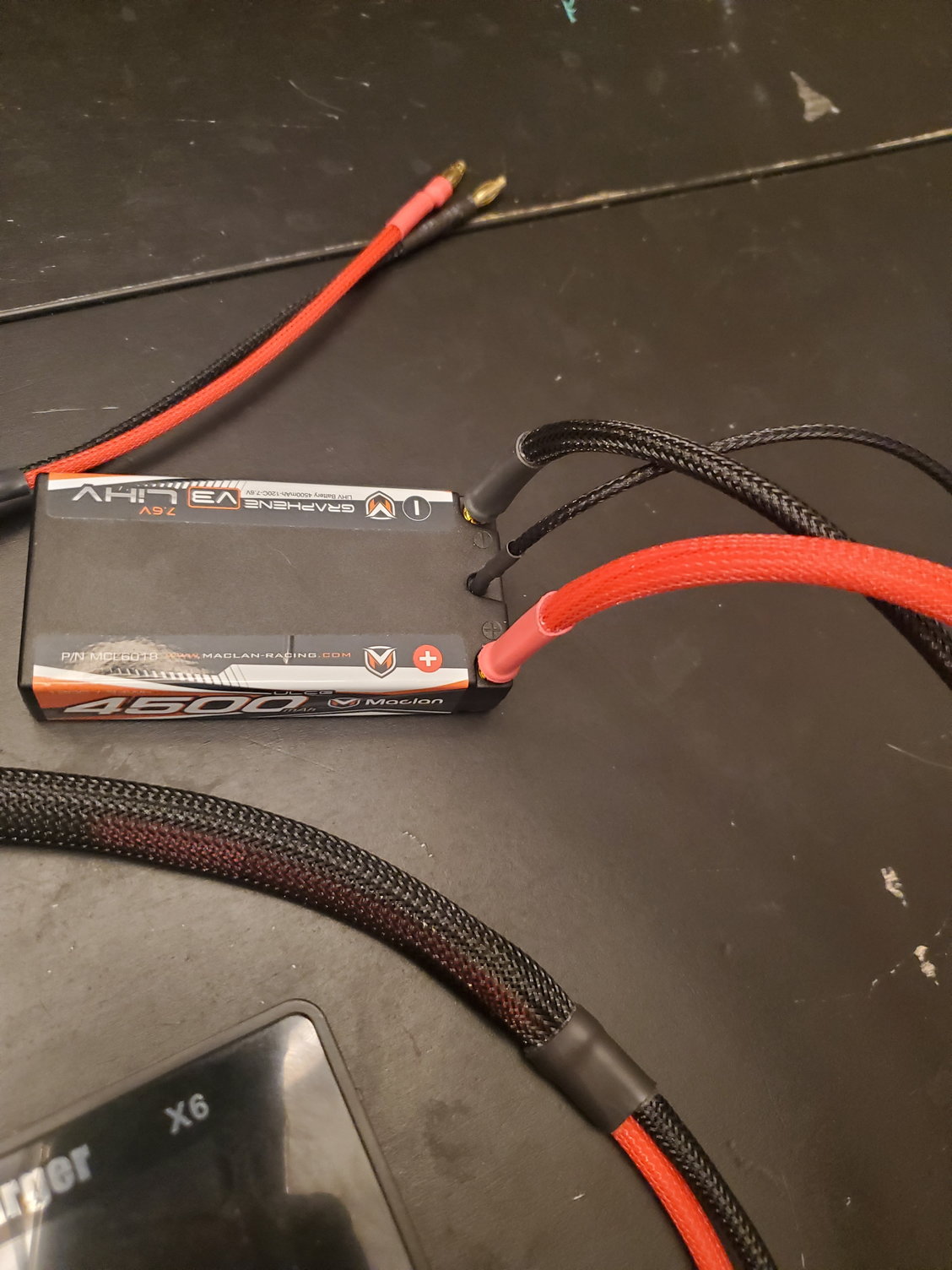
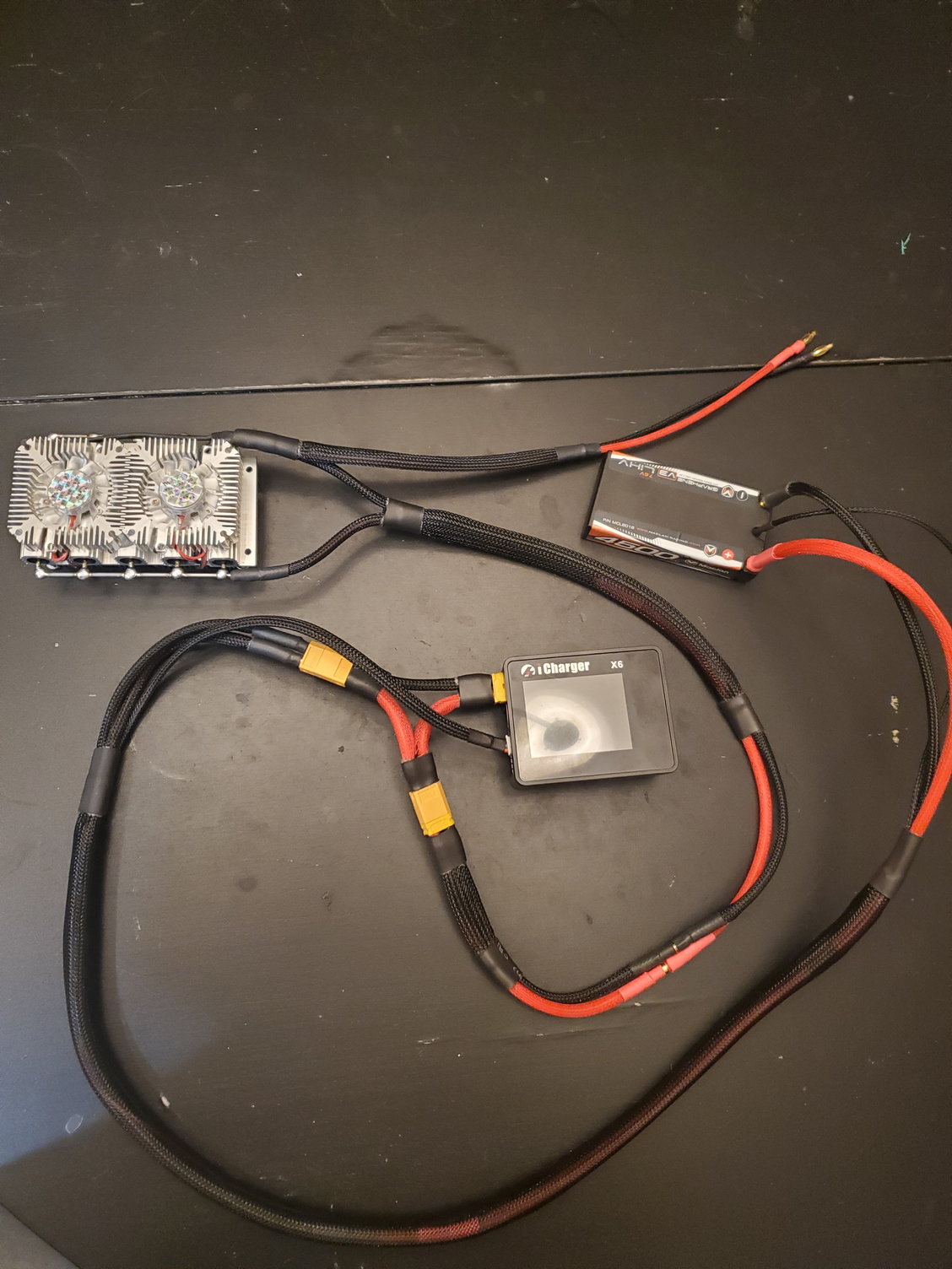
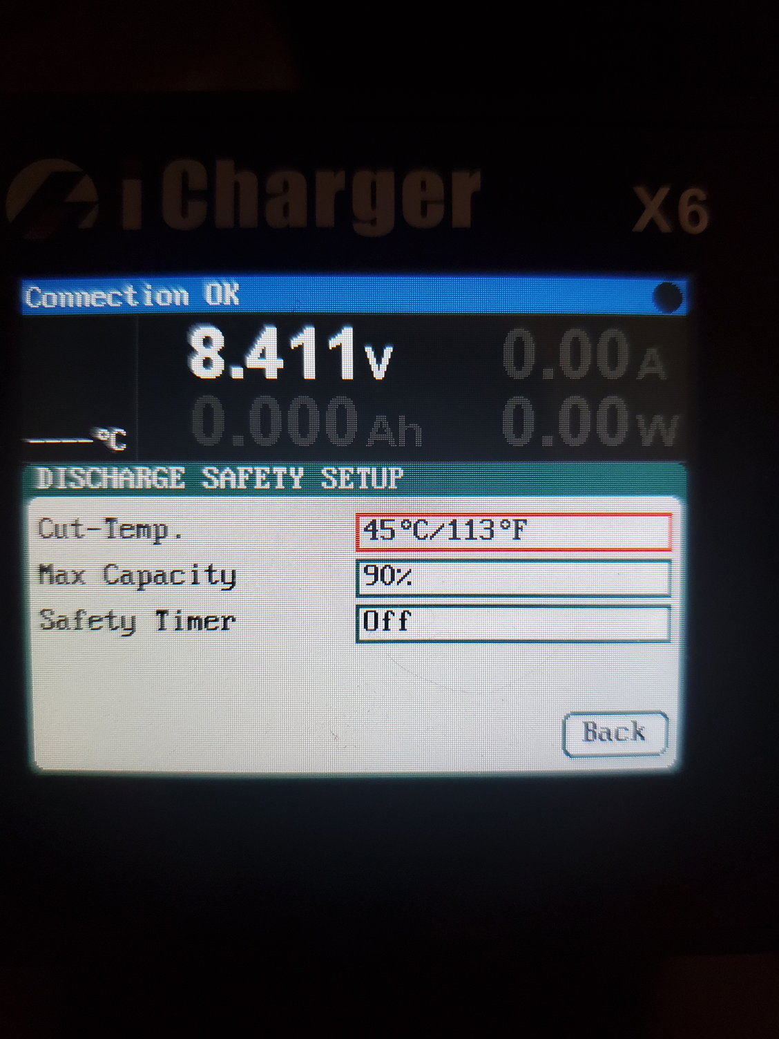
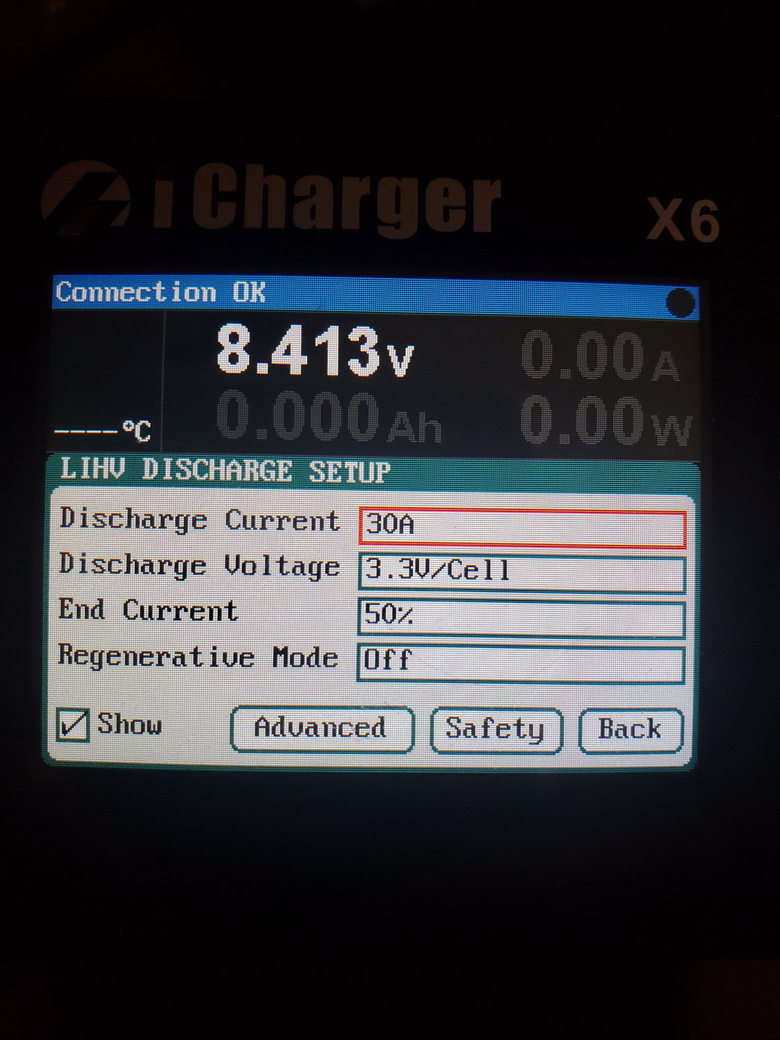
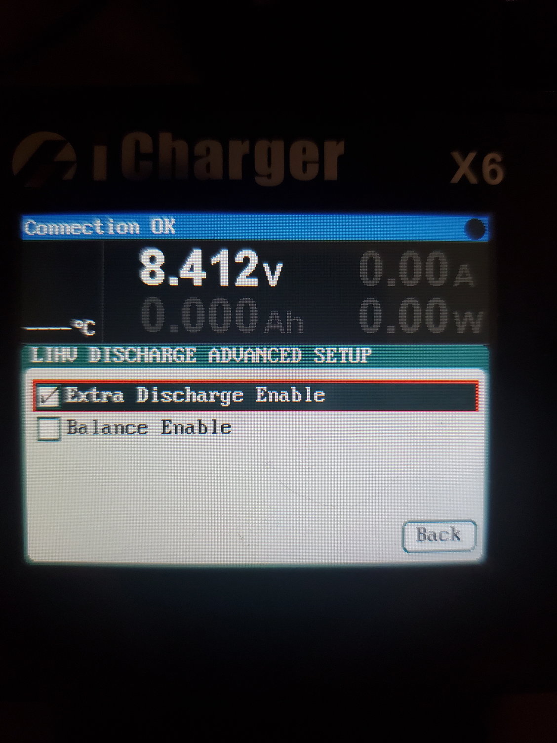
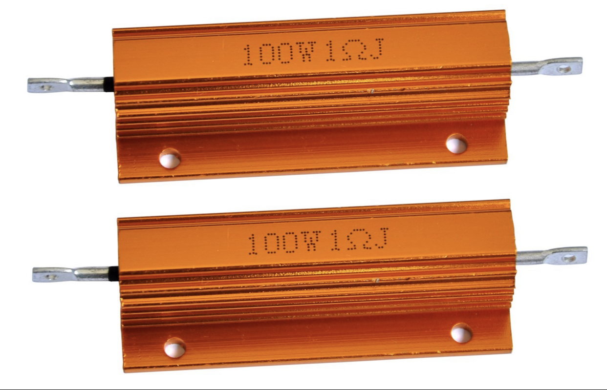
I'm having similar issues to others with my X6. I'm trying to externally discharge 2S LiHV batteries at 30A with an RL Power resistor bank, but I am unable to discharge above 4.3A. The discharge rate initially starts at 30A then quickly drops to around 4A. I have updated the firmware to 2.0.4 beta 2 which didn't help and I've updated to 2.0.7 with no success. The resistor bank is in series with the battery on the positive lead as the manual states and I have the balance lead directly connected between the battery and the charger. I've followed the settings shown in the previous posts by Marcos with no luck. Any other recommendations to try? TIA
Last edited by Marcos.J; 02-09-2020 at 09:32 AM.
 02-09-2020, 06:00 PM
#342
Tech Initiate
iTrader: (2)
I spent some time this evening and simplified my wiring. No improvement.
I purchased the resistor bank assembled and can't verify exactly what the resistance is of each individual resistor. I did measure the resistance of the entire discharge bank at 0.2 ohms which is the correct resistance for five 1 ohm resistors wired in parallel, so I think the discharge bank is okay.
I also reverted the firmware back to the 2.0.4 beta2 that seemed to help some people. When I did this and ran the discharge, I got an error stating 'Input over voltage'. Loading the 2.0.7 firmware again eliminated this. Not sure if this is relevant to my issues or not.
Anyway, thanks to everyone for all of the help, but I think I'm done with this charger.
02-09-2020, 06:42 PM
#343
Looking at your setup I have version 2.08 and I built my resistor bank with just (4) 1 ohm resistors. I am new to external discharging but your setup wiring wise looks right as well as your settings. I see alot of other 5 resistor setups in this forum so they must work but what I noticed on mine is if I setup the max amperage on mine for lets say 18 amps it will just discharge at 4 amps or so. If I set it for 30 it runs at the highest it can based on the resistor bank resistance and voltage (I=V/R). My guess is that the X6 can turn on and off the load but it cant throttle it (or at least much). So if the amperage goes over the setpoint (in my example 18 and in yours 30) that it has to just use the lower internal discharge limitation for the amps/watts.
What could be happening with your setup is that even with the setpoint of 30 amps your resistance is to low and the problem might be compounded with the HV packs having a higher nominal voltage. At least that's my 2 cents. Maybe start a discharge cycle from a storage voltage and see if you can get more then 4 amps. Lowering the "V" will result in a lower potential amperage.
You may also want to try hooking your charger power source to a larger battery (like a car battery) and charger the battery then do a regenerative discharge. I haven't personally done this but it would take out the load bank from the equation as the problem.
02-10-2020, 06:28 AM
#344
Tech Initiate
iTrader: (2)
Looking at your setup I have version 2.08 and I built my resistor bank with just (4) 1 ohm resistors. I am new to external discharging but your setup wiring wise looks right as well as your settings. I see alot of other 5 resistor setups in this forum so they must work but what I noticed on mine is if I setup the max amperage on mine for lets say 18 amps it will just discharge at 4 amps or so. If I set it for 30 it runs at the highest it can based on the resistor bank resistance and voltage (I=V/R). My guess is that the X6 can turn on and off the load but it cant throttle it (or at least much). So if the amperage goes over the setpoint (in my example 18 and in yours 30) that it has to just use the lower internal discharge limitation for the amps/watts.
What could be happening with your setup is that even with the setpoint of 30 amps your resistance is to low and the problem might be compounded with the HV packs having a higher nominal voltage. At least that's my 2 cents. Maybe start a discharge cycle from a storage voltage and see if you can get more then 4 amps. Lowering the "V" will result in a lower potential amperage.
You may also want to try hooking your charger power source to a larger battery (like a car battery) and charger the battery then do a regenerative discharge. I haven't personally done this but it would take out the load bank from the equation as the problem.
What could be happening with your setup is that even with the setpoint of 30 amps your resistance is to low and the problem might be compounded with the HV packs having a higher nominal voltage. At least that's my 2 cents. Maybe start a discharge cycle from a storage voltage and see if you can get more then 4 amps. Lowering the "V" will result in a lower potential amperage.
You may also want to try hooking your charger power source to a larger battery (like a car battery) and charger the battery then do a regenerative discharge. I haven't personally done this but it would take out the load bank from the equation as the problem.
02-10-2020, 08:48 AM
#345
Cool good to hear.
Yeah when you buy the amazon resistor pack they come in a pack of 5. I ran my wires long and just used 4 to start with the intent to add a 5th if I ever got a 40 amp duo (I cut these down much less since the picture was taken). I will slip on the 5th tonight and see if I get similar results in it going into a safety mode.
For you easy enough for you to snip off the last and solder back in if needed later. I am not sure exactly how the 5 resistor setups and the versions RL power work exactly to get 30 amps on the money.....until then I am not going to lose sleep on missing out an extra amp or two.
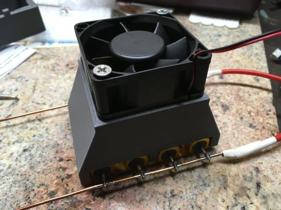