


How to port a Nitro Engine
 12-01-2008, 09:30 AM
#1
I thought I had seen these here somewhere before (heck, I thought I GOT them from here lol) but I did multiple searches and came up with nothing so here they are for the world to see once again in their full-color glory!
I dunno how well this is going to work for posting them, if anyone wants the originals let me know.
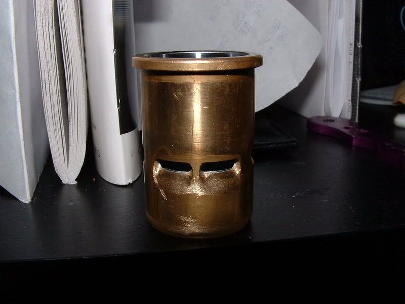
Also, here are some pics of the porting job I did on my old savage .25... it went from "Yah this truck is fun" to "Holy crap! It's ALIVE!!!"
also see here for more info Nitro engine mod
Engine mode
Image and info taken from rcuniverse.
I dunno how well this is going to work for posting them, if anyone wants the originals let me know.
Also, here are some pics of the porting job I did on my old savage .25... it went from "Yah this truck is fun" to "Holy crap! It's ALIVE!!!"
also see here for more info Nitro engine mod
Engine mode
Image and info taken from rcuniverse.
 12-01-2008, 02:25 PM
#2
 12-01-2008, 02:51 PM
#3
12-01-2008, 06:06 PM
#4
mmm...
cranktiming by modifying the crankcase in the hole under the carburator.

whats the diffren if i just add more shims.
cranktiming by modifying the crankcase in the hole under the carburator.
whats the diffren if i just add more shims.
12-01-2008, 11:10 PM
#6
It gives a better spread of the combustion and with that a wider powerband.
Just do a google search to "Singh grooves"
Just do a google search to "Singh grooves"
09-07-2010, 04:23 AM
#7
Tech Initiate
Hey Roelof,
You stated that wider exhaust ports make a difference in rpm without changing the powerband. So, how would you go about an exhaust port that is like an irregular hexagon or irregular polygon...tapered..? Would you end up making it square via width only....?
You stated that wider exhaust ports make a difference in rpm without changing the powerband. So, how would you go about an exhaust port that is like an irregular hexagon or irregular polygon...tapered..? Would you end up making it square via width only....?
09-07-2010, 05:18 AM
#8
Only the upper edges need to be widened, else you get problems with the intake ports near the exhaust ans also the upper line of the exhaust is determing the timing. With a small 2mm diamond grinding bit and a dremel it is easy to get an extra 2 or 3mm wider on each side comming out just above the intake ports.
The angle on the exhaust port is also for giving a better support to the piston, if you make it square angle there is a high risk the piston will grab itself into the port.
The angle on the exhaust port is also for giving a better support to the piston, if you make it square angle there is a high risk the piston will grab itself into the port.
09-10-2010, 06:20 AM
#9
Tech Initiate
Hi Roelof
The way that I modifiy the crank, I do as instructed by other editorials. The closing edge of the inlet valve is knife edged, but so is the opening end = increasing the over-all opening. Because I only go as far as to the edge of the port, and not over the edge...ie, not extending the original parameters of the outer casing, is this still increasing the duration...? The port is opened up more, but it is in the original outer limit.....? Also I ground the crank cheeks extra centrifuge's to create more turbulance and crank case pressure. I have really noticed a huge difference and the exhaust exits very strong and fast stream of smoke. The response is very crisp and snappy. Im still running the engine in, but after one tank on low rpms, the cooling head didnt even get above 60 degrees temp. I was amazed. I also match-ported the inlet port to the carburettor and ported the sleeve as well. In addition to this, I ground out the transfer channels in the crank case to match the ports on the sleeve, as I find that most engines are not properly done. This engine is a SH CXP.28-P6. Im now experimenting with an Associated Pro 8.0 .50, seeing if I can get some more RPM's out of the torque monster. If I cant, then at least it will be more responsive and have more power. I widened the exhaust port just as you said, but this time Im trying something different with the crank cheeks, not so cut up. But I know that I wont get the same crank case pressure as the previous engine I did. I actually cant believe how well that little engine absolutely pumps the gases out....!! Thanks for all your advice, I have learned to much and this is heaps of fun on my rainy days....!!!
The way that I modifiy the crank, I do as instructed by other editorials. The closing edge of the inlet valve is knife edged, but so is the opening end = increasing the over-all opening. Because I only go as far as to the edge of the port, and not over the edge...ie, not extending the original parameters of the outer casing, is this still increasing the duration...? The port is opened up more, but it is in the original outer limit.....? Also I ground the crank cheeks extra centrifuge's to create more turbulance and crank case pressure. I have really noticed a huge difference and the exhaust exits very strong and fast stream of smoke. The response is very crisp and snappy. Im still running the engine in, but after one tank on low rpms, the cooling head didnt even get above 60 degrees temp. I was amazed. I also match-ported the inlet port to the carburettor and ported the sleeve as well. In addition to this, I ground out the transfer channels in the crank case to match the ports on the sleeve, as I find that most engines are not properly done. This engine is a SH CXP.28-P6. Im now experimenting with an Associated Pro 8.0 .50, seeing if I can get some more RPM's out of the torque monster. If I cant, then at least it will be more responsive and have more power. I widened the exhaust port just as you said, but this time Im trying something different with the crank cheeks, not so cut up. But I know that I wont get the same crank case pressure as the previous engine I did. I actually cant believe how well that little engine absolutely pumps the gases out....!! Thanks for all your advice, I have learned to much and this is heaps of fun on my rainy days....!!!
09-10-2010, 06:30 AM
#10
Tech Initiate
Photo's continued...
09-10-2010, 07:45 PM
#11
Tech Initiate
What would happen if you widened the inlet and boost ports and the channels to match....?
09-11-2010, 01:39 AM
#12
Not much I think. The boost ports have a small funtion to get some mixture and pressure out from under the piston. Some do cut off a lot from the under edge of the piston to save weight and get the boost thing over a very wide area using the intakes but the loss of weight is doing more. This is better noticeable with the high RPM onroad engines.
Be real about one thing, most factory team engines do not have all those fancy cuts, with those it is more the selection, probebly the used materials and for sure the timings.
Be real about one thing, most factory team engines do not have all those fancy cuts, with those it is more the selection, probebly the used materials and for sure the timings.
09-11-2010, 03:58 AM
#13
Tech Initiate
Yea, Ive noticed with this Team 8.0 engine (ThunderTiger BK-50) both transfer port sides of the piston skirt have cut aways. Otherwise at TDC the transfers would be closed off. The Ports on this engine are very small for its displacement. My SH.28 had larger standard ports than the .50. The timings for the 8.0 as measured are (+/-3 degrees):
Induction: Open: 210 Close: 55 Duration: 205 Degrees (Modified)
Transfer: Open: 125 Close: 250 Duration: 125 Degrees
Exhaust: Open: 110 Close: 260 Duration: 150 Degrees (widened upper corners only)
From the timings that are given here, what can you see that could make this engine rev more (apart from the Induction rotating valve as I have taken the port out to its limits already. Well MAYBE. If you view my pics prevoius post, the drawing is how I have modified it. So do you think I can change it further....????
I ran the second run-in tank through the .28 today... getting looser, and is so twitchy on the throttle. Im stoked...!!!!
09-11-2010, 07:44 AM
#14
Tech Initiate
Hey Roelof
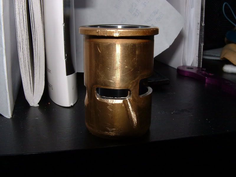
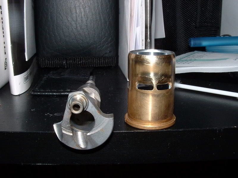
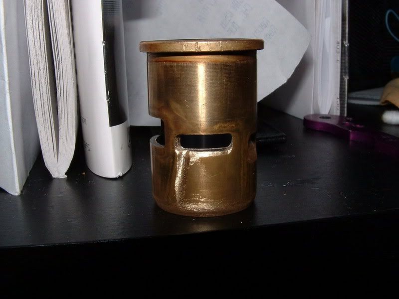
Here's the last of the work on the AE PRO 8.0. I ported the liner as you recommended and matched the transfer channels to the transfer ports. The crank mods are on the previous post. Its the crank with the 3 fangs, and the induction valve is there too. I will try the engine with the crank as is, but if im not satisfied, I'll cut it up like the previous. Do you think I have room for a timing adjustment in the Induction valve port, or have I taken it too far for further. I havent changed the duration, only opened up what wat already there. But both the opening and closing are knife edged....
I really want this thing to gain some rpms. I opened up the exhaust manifold as well, match ported it to the exhaust port.
09-11-2010, 07:54 AM
#15
Tech Initiate
The head on the 8.0 is the one pictured previous post with the 3 grooves. On the SH.28 I did that exactly as you did yours. There's also a pic of the MGT 8.0 with my revised body work.