


 76Likes
RC Crew Chief Software
 10-16-2017, 10:29 AM
#706
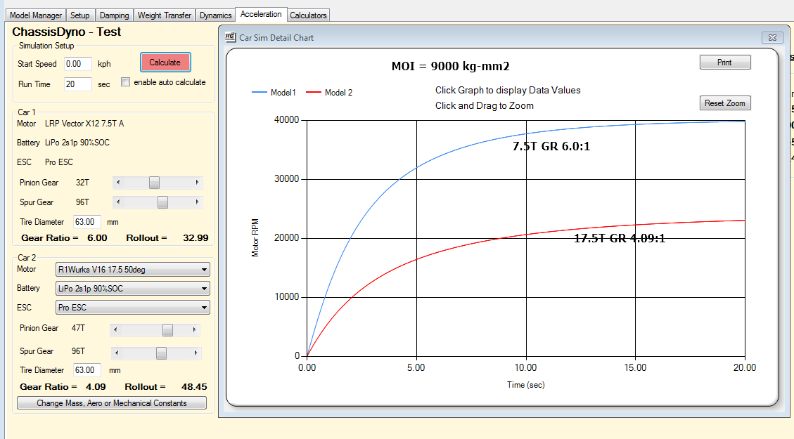
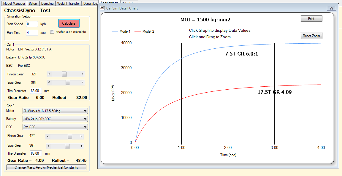
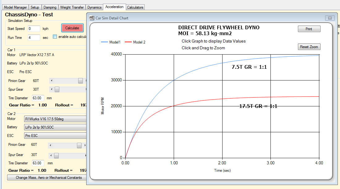
Couple things. You want to target the Mass Moment of Inertia (MMI) not just the Mass. The MMI is what determines how much resistive load the motor must accelerate. Yes mass is part of it but the equation to calculate MMI for a solid cylinder is 1/2 * mass * radius squared. The radius squared term has a big impact. I shoot for a spin up time of 2-4 seconds which is similar to what you see on track. So to answer your question about your current set up with a MMI of .009 kg-m2 (9000 kg-mm2) I would say yes that is too high. I ran some simulations using a 7.5T and 17.5T motor to compare your current setup to one with 1500 kg-mm2 which is what I would recommend. There are three graphs below. The last one shows the setup I currently use with my modified MD2 flywheel dyno.
According to the sims your rig will take 15-20 seconds to reach constant speed. IMO that is too long. Repeated runs will cause motor heating which will affect comparative results. Also if you are using a battery as a power source it will lose enough charge after a few runs to affect repeatability. It will also take a lot of energy to slow down the dyno so I wouldn't use the motor to do this.
In my setup I use a 50hz variable frequency sample rate and the Serial port baud rate of 115200. I can easily do 10 consecutive runs on a 2S Lipo with near zero effect on repeatability.
Hope this helps.
Sim of your current setup with MMI of 9000
Your setup with MMI of 1500
My modified MD2 Motor Dyno with 50mm dia Flywheel
 10-16-2017, 06:14 PM
#707
Bob, thank you for this explanation. Not having a clear understanding of all the requirements has proven to be a costly mistake on my part. That being said, I am still motivated to get it right, and will do so. I've come up with a solution using my existing setup and will post those modifications.
The toughest part of my current setup has been the rollers, getting them balanced correctly. The solution, I've come up I believe will be better.
as for sampling in 50hz, this is something I haven't looked at. Would the code used for your setup work on Arduino? I have an Uno, and use an interrupt with a 10k resistor.
Last edited by MaxRain; 10-16-2017 at 06:28 PM.
10-16-2017, 06:19 PM
#708

Bob have you considered making a conversion for the MD2 dyno available using the set up you have? Something I know I'd be keen on getting if it aids my motor tuning, sadly I lack the engineering expertise to even know where to begin on doing this sort of thing myself.
10-17-2017, 04:14 AM
#709
Bob, thank you for this explanation. Not having a clear understanding of all the requirements has proven to be a costly mistake on my part. That being said, I am still motivated to get it right, and will do so. I've come up with a solution using my existing setup and will post those modifications.
The toughest part of my current setup has been the rollers, getting them balanced correctly. The solution, I've come up I believe will be better.
as for sampling in 50hz, this is something I haven't looked at. Would the code used for your setup work on Arduino? I have an Uno, and use an interrupt with a 10k resistor.
The toughest part of my current setup has been the rollers, getting them balanced correctly. The solution, I've come up I believe will be better.
as for sampling in 50hz, this is something I haven't looked at. Would the code used for your setup work on Arduino? I have an Uno, and use an interrupt with a 10k resistor.
I can send you my Arduino code to but it will need to be modified to suit your setup. I use a interrupt as well tied to a counter for RPM measurement. The voltage and current sensor will be different as I use an Attopilot sensor for this.
10-17-2017, 04:26 AM
#710
Beyond that you need an Attopilot VI sensor and an Arduino Uno to use to capture the data and communicate with the laptop. There are a few bits of electronics required too, OPAmp and some resistors.
This is still really pretty crude and could be improved upon particularly in the voltage and current sensing area to improve the accuracy.
10-31-2017, 08:21 PM
#712
Bob, been watching the science of setup series to re-educate myself on everything available in RC3.
Question with regards to roll stiffness. One of my chassis T3 EU measures up to have a roll stiffness number that is less than 1, closer to 0.5-0.6, race ready weight at 1350g for stock. Can't get the roll stiffness higher to 1.0 very easily. Should I be concerned with this?
I see that many of the newer kits have a roll stiffness that is equal or greater than 1. This brings me to my next question, was the Losi TypeR released ahead of its time? As the roll stiffness is in the same range of many of these kits?
By the way, still working on finishing the dyno, life has gotten in the way of completing the new mod's. Getting close though. Will post photos soon.
11-04-2017, 06:06 AM
#713
Bob, been watching the science of setup series to re-educate myself on everything available in RC3.
Question with regards to roll stiffness. One of my chassis T3 EU measures up to have a roll stiffness number that is less than 1, closer to 0.5-0.6, race ready weight at 1350g for stock. Can't get the roll stiffness higher to 1.0 very easily. Should I be concerned with this?
I see that many of the newer kits have a roll stiffness that is equal or greater than 1. This brings me to my next question, was the Losi TypeR released ahead of its time? As the roll stiffness is in the same range of many of these kits?
By the way, still working on finishing the dyno, life has gotten in the way of completing the new mod's. Getting close though. Will post photos soon.
Question with regards to roll stiffness. One of my chassis T3 EU measures up to have a roll stiffness number that is less than 1, closer to 0.5-0.6, race ready weight at 1350g for stock. Can't get the roll stiffness higher to 1.0 very easily. Should I be concerned with this?
I see that many of the newer kits have a roll stiffness that is equal or greater than 1. This brings me to my next question, was the Losi TypeR released ahead of its time? As the roll stiffness is in the same range of many of these kits?
By the way, still working on finishing the dyno, life has gotten in the way of completing the new mod's. Getting close though. Will post photos soon.
11-04-2017, 11:57 AM
#714
Does anyone have a GT8 model, did not find one in the model list.
11-05-2017, 06:07 PM
#715
The suspension geometry of the T3 eu version is different than that of the 2012 version. This is predominantly in the camber link lengths, which are shorter. This I believe makes the car more responsive, hence the difference I feel when switching chassis, between a T4 and then to the T3.
I had a look at the roll sensitivity issue. I imported the T3 model from the website and the roll sensitivity for the included setups is in the .9 to 1.2 range. For you to be seeing values in the .5-.6 range I would suspect that the CG height has been set to low as this will has a big impact on the roll sensitivity value. All the TC's I have measured have a CG height in the 29-31mm range. The model on the website is set to 31mm.
11-06-2017, 04:31 AM
#716
The suspension geometry of the T3 eu version is different than that of the 2012 version. This is predominantly in the camber link lengths, which are shorter. This I believe makes the car more responsive, hence the difference I feel when switching chassis, between a T4 and then to the T3.
If you want a definitive answer you could email me the T3 model and I will have a look.
11-09-2017, 10:14 PM
#717
I started playing with RC3 the other day so I can compare geometries between my TC3 and TC5 to figure out why they behave so differently. Problem is, the chassis models on the website for those cars don't include the steering geometry, and some of the basic parameters on the TC3 are so far out (eg wheelbase is wrong by more than 5mm for kit setting) that I can't really trust any of the numbers. Not a dealbreaker, I'll just have to measure the whole car from scratch. I kind of needed to measure some of that already as I have a partial TC4 front end (shock tower and inner camber link braces).
The bigger problem though is that the TC5 uses a single bellcrank system. There's no facility to specify that in RC3. Are there any plans to implement this?
While I was trying to experiment with the bellcrank numbers to see if I could fudge something close to a singe bellcrank, I entered a 0 in one of the fields. The software didn't like that and I got stuck in an infinite loop of error messages notifying me that calculations were overflowing. I had to kill the process with task manager, losing all my unsaved changes. The UI should probably catch these errors and revert the number back to the previous valid value to avoid infinite loops such as this.
 11-10-2017, 01:10 AM
#718
I've got several versions of the Xray T1 and tamiya tl01 which I'd like to model but haven't attempted as, like the tc5, they both use a single bellcrank steering system. It's the only thing stopping me from purchasing RC crew chief at the moment.
11-10-2017, 01:59 AM
#719
11-10-2017, 04:49 AM
#720
I've found a workaround that seems to do the job. Set Xb to a very small value (eg 0.01) - unfortunately everything goes crazy when you set it to zero. Set XRack to an arbitrary large-ish number (eg 20mm). Do some basic trigonometry to figure out the value of Rb to get the right length of the bellcrank arm. The ackermann preview window will render some parts of the bellcrank a bit weird when you change the steering angle, but the geometric values all appear to work correctly.
I will add a lower limit to the Xb permitted range.

