


 92Likes
RWD M-Chassis, 1/12th inspired
 12-15-2022, 12:46 PM
#31
Its not clear to me from the original images - did you have the servo affixed to the rear pod/cross member? Or was the cross member affixed to the main chassis?
If the servo was attached to the floating portion of the rear suspension - that would also introduce another odd variable to interact with the steering rod angles.
I think its a critical characteristic that the steering servo be firmly mounted to the same plane(chassis plate) as your steering mechanics.
Whatever that solution is, definitely requires more thought.
Last edited by simple; 12-16-2022 at 04:24 AM.
 12-15-2022, 01:00 PM
#32

It isn't a design that lacks for innovation, but sometimes simple is best.
Reducing part count, especially moving parts, is a good way to reduce failure modes and slop. Also this design appears to put lowering the CG of the car as about fourth on the list of criteria, with saving weight about fifth. Pan cars just flat out don't need a complicated suspension method.
The adjustability is admirable but not as useful as some may think. Moving the battery back and forth may not be worth the complexity and volume in the car dedicated to that parameter.
12-15-2022, 01:19 PM
#33
Its not clear to me from the original images - did you have the servo affixed to the rear pod/cross member? Or was the cross member affixed to the main chassis?
If the servo was attached to the flaoting portion of the rear suspension - that would also introduce another odd variable to interact with the steering rod angles.
I think its a critical characteristic that the steering servo be firmly mounted to the same plane(chassis plate) as your steering mechanics.
Whatever that solution is, definitely requires more thought.
Is a >60% rear weight bias desirable?
12-16-2022, 04:48 AM
#36
I think the option to have it adjustable is more important than the qty.
Also, the steering servo is a small percentage of the load mass on a car of this scale. Not sure if its location is of significant value to be placed in an aft chassis location. You may be forcing yourself into other compromises if considering it a relevant mass.
Also, the steering servo is a small percentage of the load mass on a car of this scale. Not sure if its location is of significant value to be placed in an aft chassis location. You may be forcing yourself into other compromises if considering it a relevant mass.
12-16-2022, 05:32 AM
#37
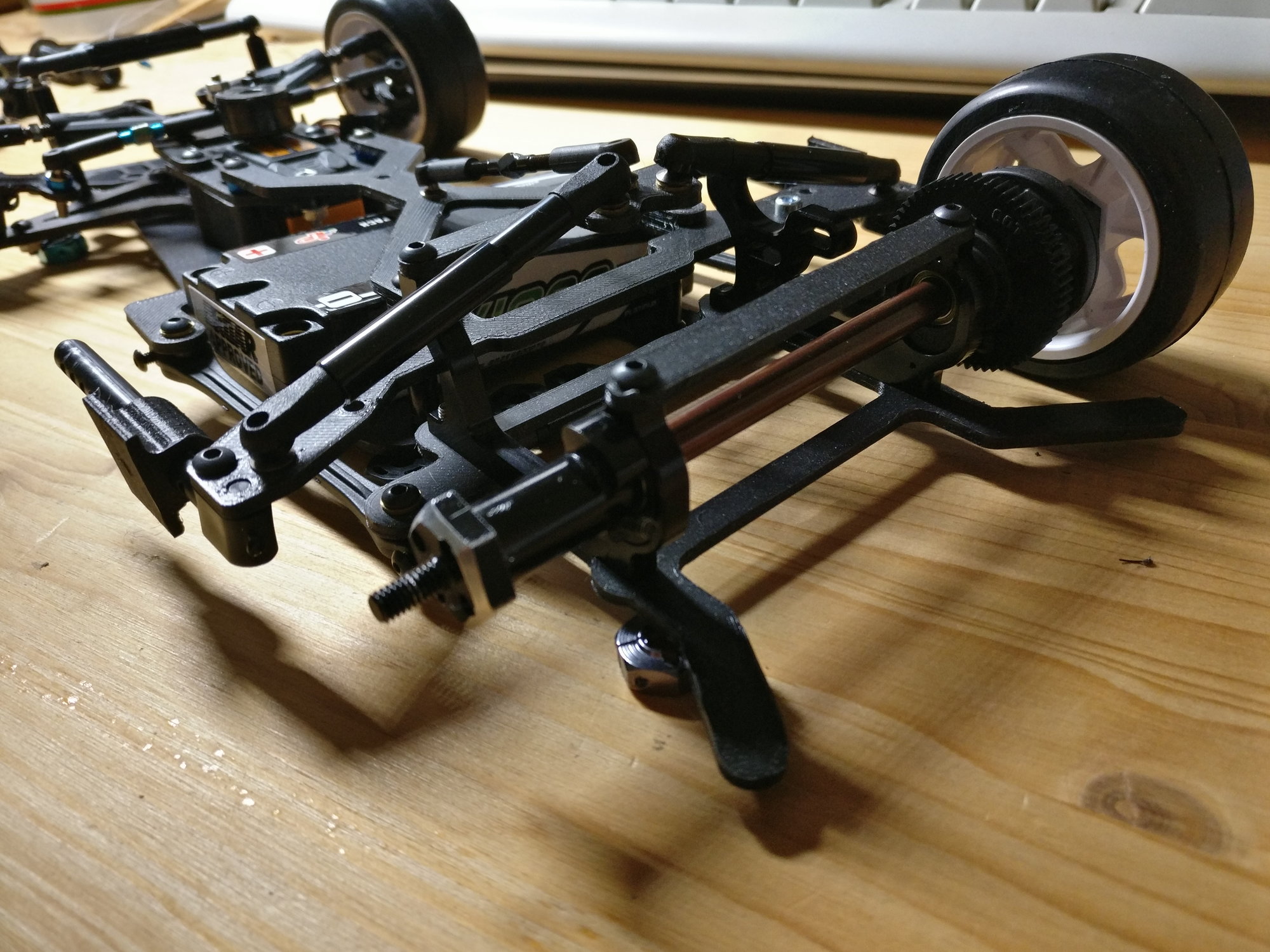
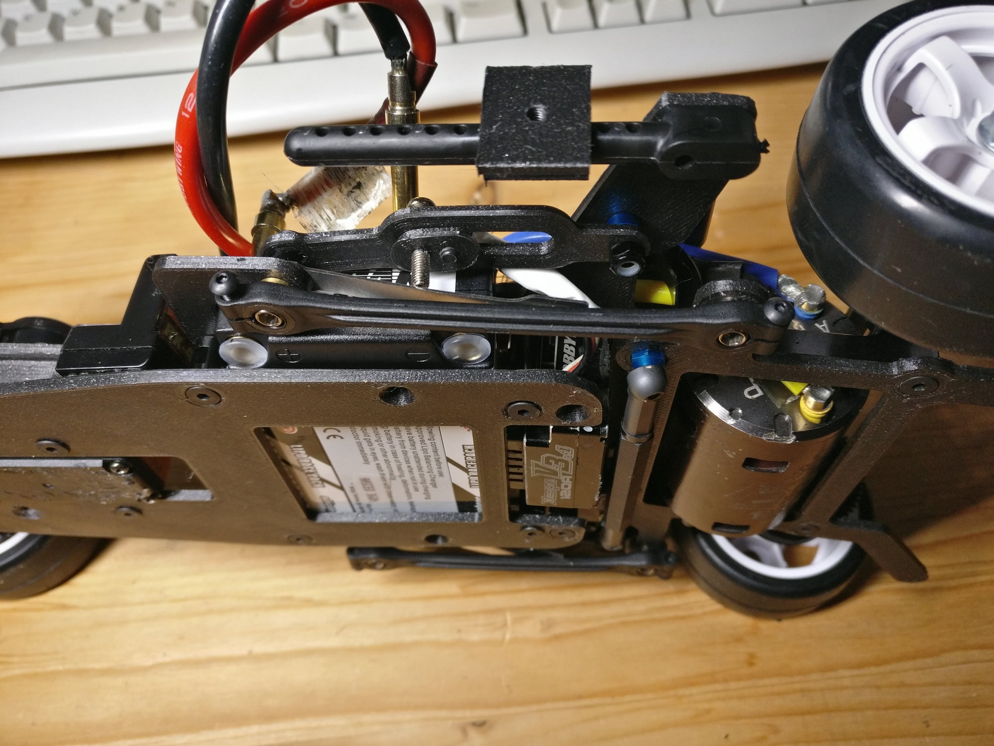
well the placement of the servo came naturally once I found out I wanted the ESC behind the battery. This came as I wanted a Rear weight bias similar to the fwd cars (due to a lack of information about pan car weight distribution). of course it's more complex than mounting it in the front, but then with the rear servo I am less limited with the front suspension...
Thanks all for sharing your thoughts! Much appreciated!
Thanks all for sharing your thoughts! Much appreciated!
12-16-2022, 11:23 AM
#38
Tech Addict
Cool stuff. But to truly make it interesting you should make it RR layout 
12-17-2022, 01:57 AM
#39
Well first of all thanks to all contributors to this change. I always appreciate your comments, thoughts and recommendations.
I made up my mind and changed the components layout to a FWD servo attachment, with a direct link to the steering arms. The steering linkage weighs around 10g, and so I invested these 10g in a servo mount up front. The ESC has come to the mid-rear position, the receiver and laptimer still need placement.
For the side links front ball, I still think if I should mount them to the rear cross carbon piece, or have a separate mount further front of the chassis. If it's mounted on the rear cross piece, I can move the battery fore/aft freely by 25mm (=2.5% weight bias change roughly). If they are mounted to some standoff at the chassis, I need to move those parts once I move the battery.
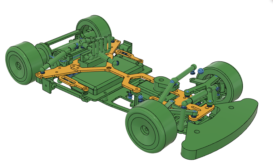
New components layout. The servo can move fore-aft with the upper front bulkhead.
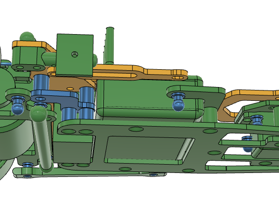
A bit more clarity on the front suspension. Option to go kingpin is intact, but hardly any lighter.
Rear corner view. Still messing with the side link attachment...
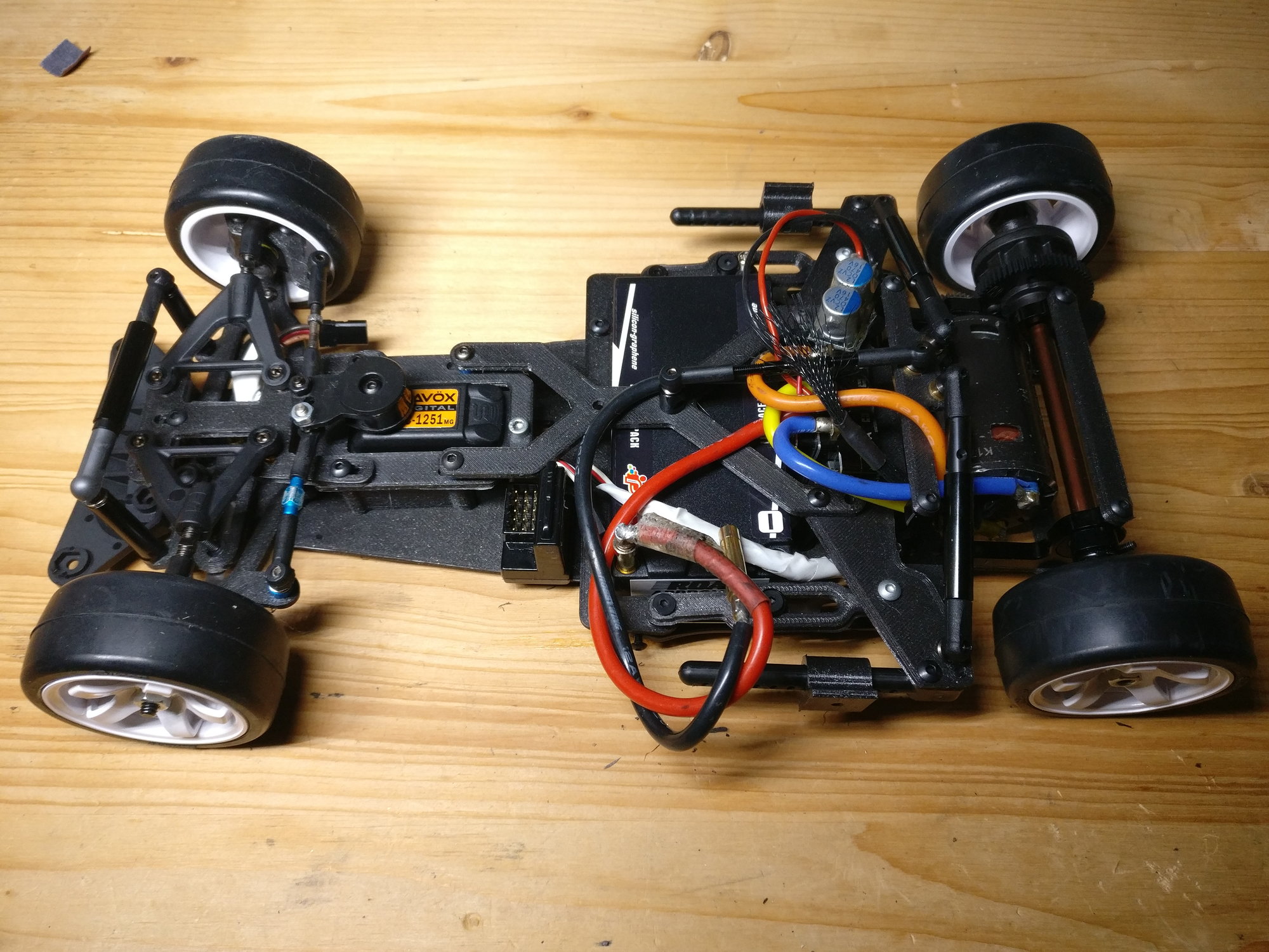
The servo is recessed into the chassis, so CG wise I am pretty close to a lying servo.
The idea with the side links explained:

Rear battery clamps

Same clamps reversed, for front bat position.
I made up my mind and changed the components layout to a FWD servo attachment, with a direct link to the steering arms. The steering linkage weighs around 10g, and so I invested these 10g in a servo mount up front. The ESC has come to the mid-rear position, the receiver and laptimer still need placement.
For the side links front ball, I still think if I should mount them to the rear cross carbon piece, or have a separate mount further front of the chassis. If it's mounted on the rear cross piece, I can move the battery fore/aft freely by 25mm (=2.5% weight bias change roughly). If they are mounted to some standoff at the chassis, I need to move those parts once I move the battery.
New components layout. The servo can move fore-aft with the upper front bulkhead.
A bit more clarity on the front suspension. Option to go kingpin is intact, but hardly any lighter.
Rear corner view. Still messing with the side link attachment...
The servo is recessed into the chassis, so CG wise I am pretty close to a lying servo.
The idea with the side links explained:
Rear battery clamps
Same clamps reversed, for front bat position.
Last edited by h2e; 12-17-2022 at 02:24 AM.
12-17-2022, 02:21 PM
#40
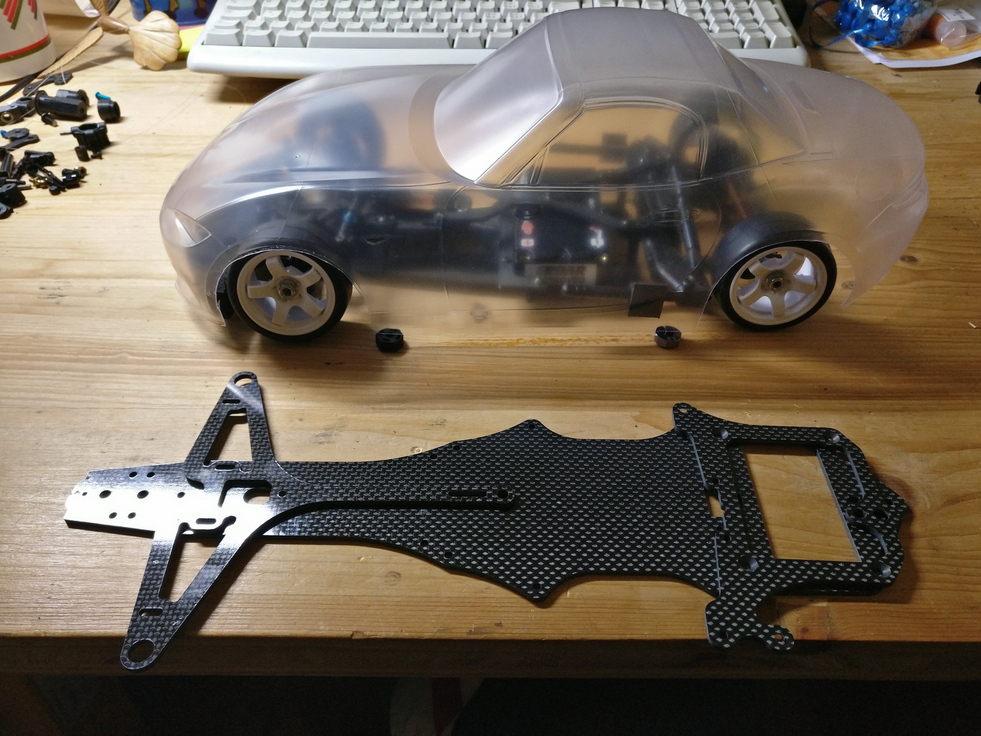
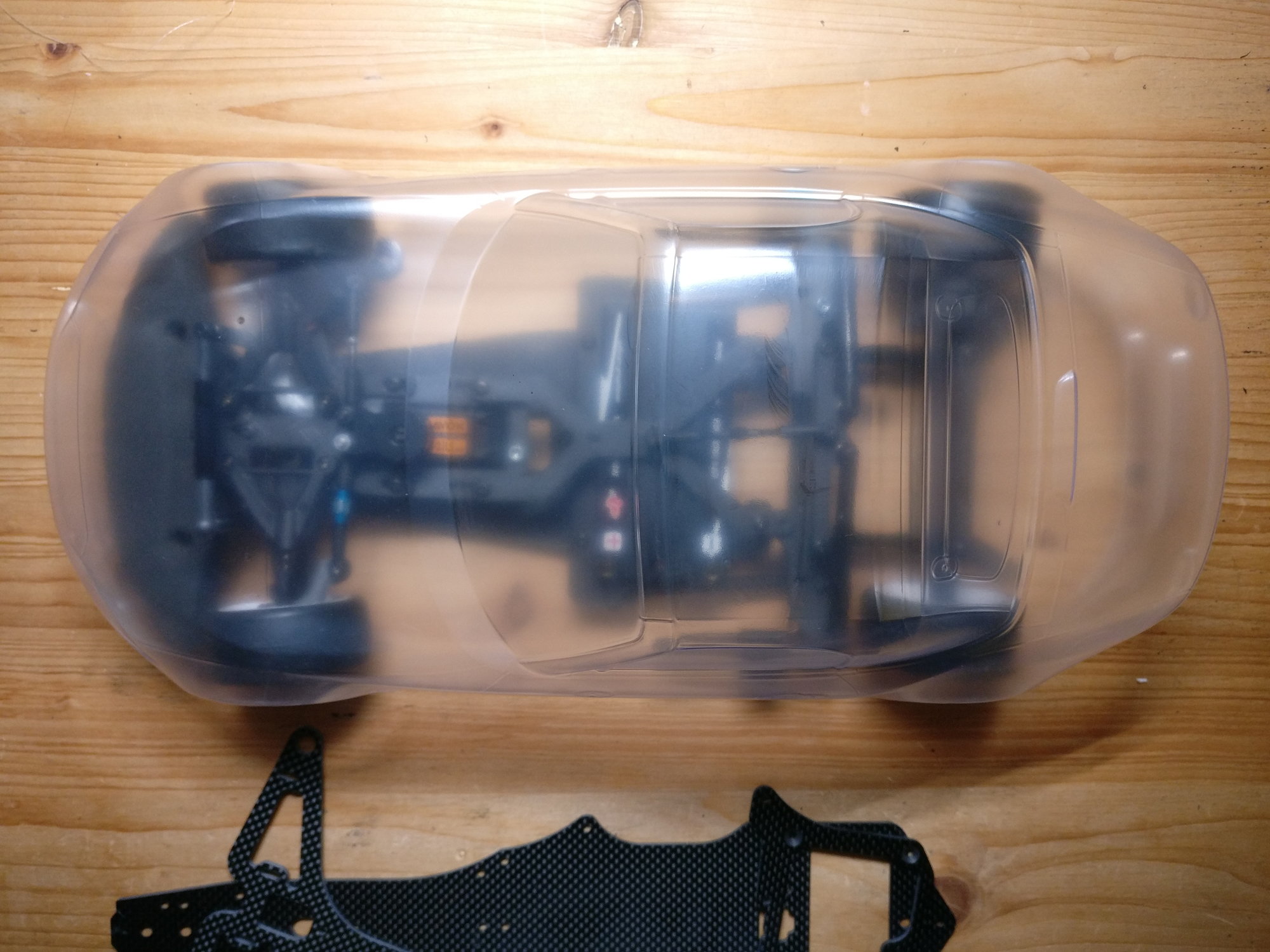
Time to mock up a bit...
Panhard rod and lower chassis view.
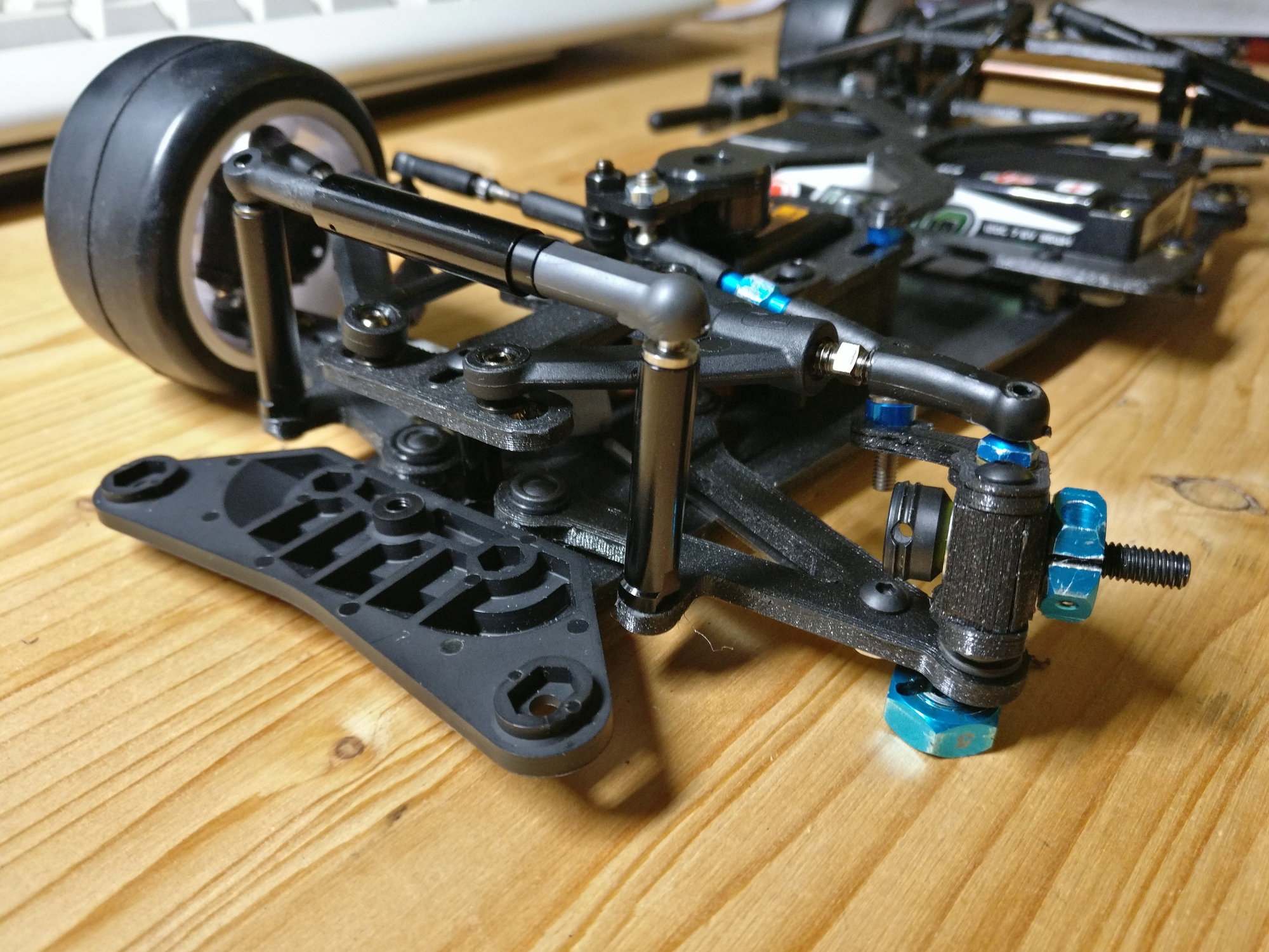
front suspension detail. the leaf spring attachment is missing.
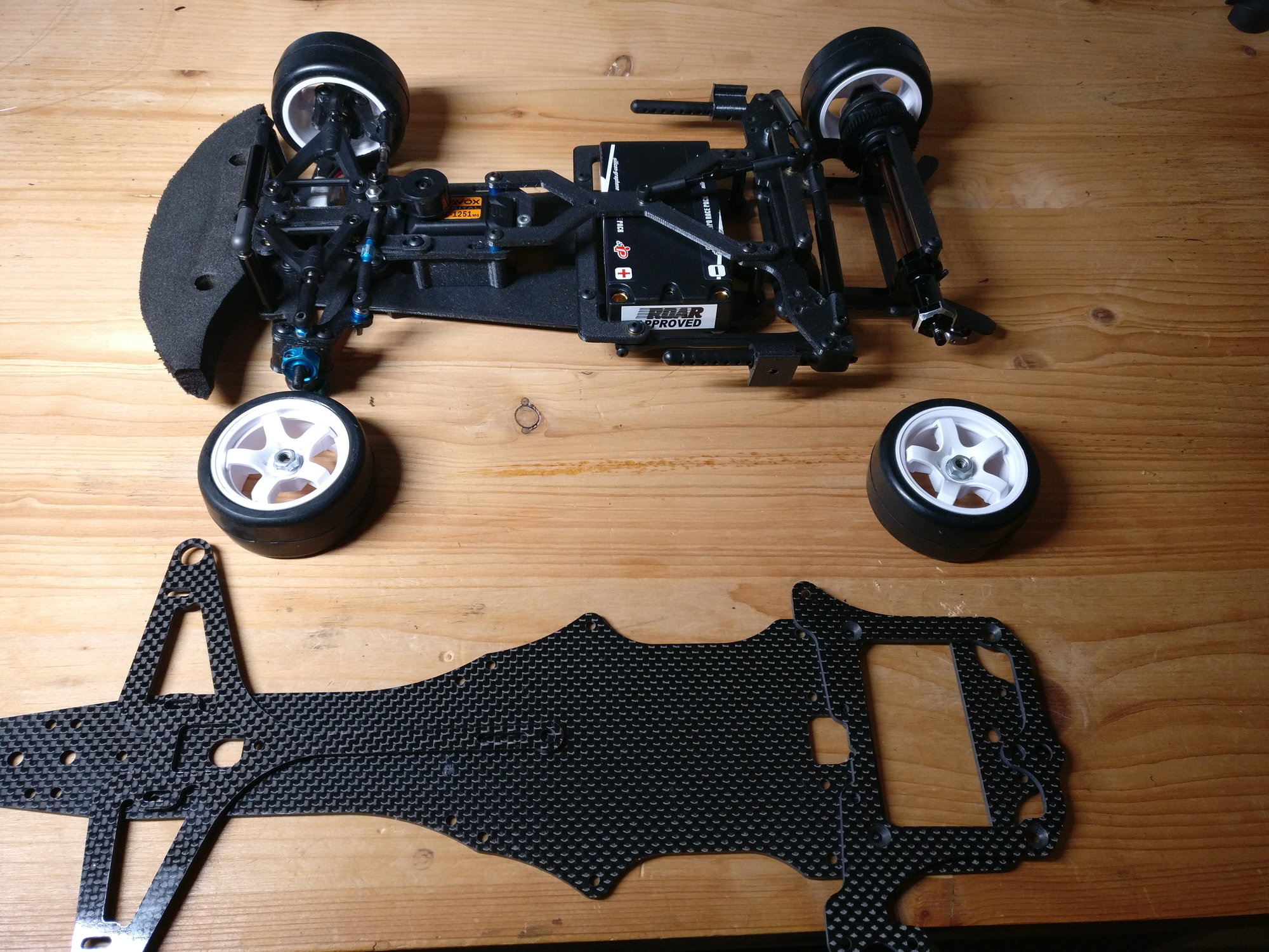
donor F1 chassis and M class interpretation.
the wheelbase is shorter than from its donor chassis...
not so much rear body structure...
Panhard rod and lower chassis view.
front suspension detail. the leaf spring attachment is missing.
donor F1 chassis and M class interpretation.
the wheelbase is shorter than from its donor chassis...
not so much rear body structure...
Last edited by h2e; 12-18-2022 at 12:03 PM.
12-19-2022, 10:16 AM
#41
Tech Initiate
Hi, I have front Axle from kawada m500gt if you Are interested . Or we used front Axle from associated short course. It was lighter and Blue😎. And I might have some crude stl of kawada steering blocks somewhere.
12-19-2022, 12:38 PM
#42
I was skeptical of this concept at first, but now I am intrigued. Looking forward to seeing more.
12-19-2022, 01:49 PM
#43
12-20-2022, 03:08 PM
#44
Added some detail to the springs and leaf spring adjusters. They are similar to an Awesomatix A800 with a guiding rail and a little slider with a "stiffness" and a "ride height" screw. Some parts got a makeover to improve edge distances, as well as clearance to other parts. Also, I stiffened up the front chassis panhard attachment.
Parts which are green I am satisfied with.
Front chassis panhard attachment. The distance to the main chassis is smaller, i.e. the load path is more direct and thus stiffer. (side link removed)
Parts which are green I am satisfied with.
Front chassis panhard attachment. The distance to the main chassis is smaller, i.e. the load path is more direct and thus stiffer. (side link removed)
Last edited by h2e; 12-21-2022 at 12:34 PM.
12-21-2022, 02:44 PM
#45
Big moment: the mockup is standing on its own feet. The front springs work really well, on the rear I am not yet sure. As the motor pod is held secured against rotation from torque, it feels rather stiffly sprung, especially tweaking the chassis takes quite some torque.
I hate wiring as you can see...
test fitted motor and springs. New side link brace.

front end suspending its own weight.
Rear panhard attachment and side link springs.
I hate wiring as you can see...
test fitted motor and springs. New side link brace.
front end suspending its own weight.
Rear panhard attachment and side link springs.