


 55Likes
Xray X1 front indepndent disc brakes
 02-08-2021, 11:00 PM
#16
Tech Regular
The cable disc brakes are a great idea. Why not try a disc hex hub like the 4-tec? There are also alloy variants of the drift hexes. You could mill those down to any diameter you need.
 02-08-2021, 11:29 PM
#17
kawasaki161 I learn something new every day  Cool experiment, but the space constraints are crazy, I have 1mm between the brake pad and the wheel, could not squeeze a moving amgnet inside there ( or a coil)
mrreet2001 No debate there, I meant that the locally generated magnetic fileld. this can only be generated locally at the wheelhub ( no driveshaft to bring the rotational motion away from the hub, hence cheating out for some more space), and for ther I don't think I can generate enough gausses to effectively stop the car, space is key here, and there isn't much
photeckk I will have the capability to produce this in small quantities, so yep, I'll make an attempt to sell this kit once it is fully grown up But not here, only through official channels, with invoices etc. Having said that, not sure about the demand, because this will be illegal everywhere with one penstroke on the racing rules. But then again, maybe I'll be lucky because tracks or race orgsanizers will endorse it, who knows 
Nerobro I'll be completely frank here, I did not checked all of the possibilities, before I started designing my brke system, as this brakeforce proportion to velocity sounds lke an absolute winner, with it's flaws ( no front brake on slow speeds), then again, it is a can of worms in it's own, with RPM levels, magnetic inductance levels, and so on, I firmly believe, that this route woud've at least double the development time for me, and it already took 4 months :d Okay, most of that time was waiting on Aliexpress to deliver, the miniature springs took an eternity to arrive. I also like the discussions, and all the ideas this commuity has ( hence my first post), I believe it truly propels us forward
This is still strongly the development phase, if any onf you can se anything fundamentally wrong with the design, now it is still easy to messs around with it in CAD, so fire away Otherwise I call this project finished, just waiting on the machining capability, so that I can create a durable enough testpiece that I can actually drive, and se if it works. Oh yeah, and the servos, I have to figure out how not to fry them ( my ide is to put some springs on thecable, damping the forces just like on the break asembly of a 1/8 buggy)
Cool experiment, but the space constraints are crazy, I have 1mm between the brake pad and the wheel, could not squeeze a moving amgnet inside there ( or a coil)mrreet2001 No debate there, I meant that the locally generated magnetic fileld. this can only be generated locally at the wheelhub ( no driveshaft to bring the rotational motion away from the hub, hence cheating out for some more space), and for ther I don't think I can generate enough gausses to effectively stop the car, space is key here, and there isn't much
photeckk I will have the capability to produce this in small quantities, so yep, I'll make an attempt to sell this kit once it is fully grown up
But not here, only through official channels, with invoices etc. Having said that, not sure about the demand, because this will be illegal everywhere with one penstroke on the racing rules. But then again, maybe I'll be lucky because tracks or race orgsanizers will endorse it, who knows Nerobro I'll be completely frank here, I did not checked all of the possibilities, before I started designing my brke system, as this brakeforce proportion to velocity sounds lke an absolute winner, with it's flaws ( no front brake on slow speeds), then again, it is a can of worms in it's own, with RPM levels, magnetic inductance levels, and so on, I firmly believe, that this route woud've at least double the development time for me, and it already took 4 months :d Okay, most of that time was waiting on Aliexpress to deliver, the miniature springs took an eternity to arrive. I also like the discussions, and all the ideas this commuity has ( hence my first post), I believe it truly propels us forward
This is still strongly the development phase, if any onf you can se anything fundamentally wrong with the design, now it is still easy to messs around with it in CAD, so fire away
Otherwise I call this project finished, just waiting on the machining capability, so that I can create a durable enough testpiece that I can actually drive, and se if it works. Oh yeah, and the servos, I have to figure out how not to fry them ( my ide is to put some springs on thecable, damping the forces just like on the break asembly of a 1/8 buggy)
02-08-2021, 11:31 PM
#18
02-09-2021, 02:50 AM
#19

The big advantage to magnetic braking as I see it, is it's a built in form of abs. At no point, can the magnets actually stop the front wheels from turning. So you'll always have "some" steering. We'll see :-) I have to many plates spinning right now to chase that down, only to have ROAR, IFMAR or USVTA ban it. :-)
02-09-2021, 01:02 PM
#20
This is a good idea. This translates servo position to brake force, as opposed to trying to manipulate motor current to produce torque.. through a gearbox... . Move servo twice as far.. get twice as much force. Also it will somewhat compensate for pad/disk wear and thickness variance in the brakes. Also... would provide limits to how much force you apply. Locking up front wheels is a good way to learn what push REALLY is.
The big advantage to magnetic braking as I see it, is it's a built in form of abs. At no point, can the magnets actually stop the front wheels from turning. So you'll always have "some" steering. We'll see :-) I have to many plates spinning right now to chase that down, only to have ROAR, IFMAR or USVTA ban it. :-)
The big advantage to magnetic braking as I see it, is it's a built in form of abs. At no point, can the magnets actually stop the front wheels from turning. So you'll always have "some" steering. We'll see :-) I have to many plates spinning right now to chase that down, only to have ROAR, IFMAR or USVTA ban it. :-)
This magnetic braking would be awesome, but I just can not see it to be crammed inside the wheel, and there really is no more space.
02-09-2021, 01:40 PM
#22
02-10-2021, 12:48 PM
#24
Last edited by mikeylama; 02-10-2021 at 10:55 PM.
02-11-2021, 11:47 PM
#25
Tech Regular
03-08-2021, 12:36 PM
#26
Hi everyone, sorry for the long drag, but it is actually surprisingly difficult to get small servos in my country, so I had to revert to Aliexpress. In the meanwhile I started designing disc brakes for my XB4 that's going to be fun I should buy me a 1/8 scale buggy, do that next.
that's going to be fun I should buy me a 1/8 scale buggy, do that next.
03-28-2021, 10:24 AM
#27
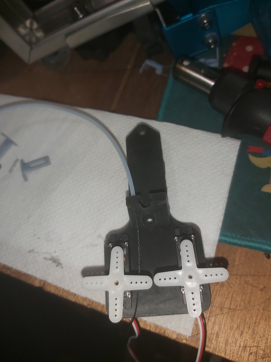
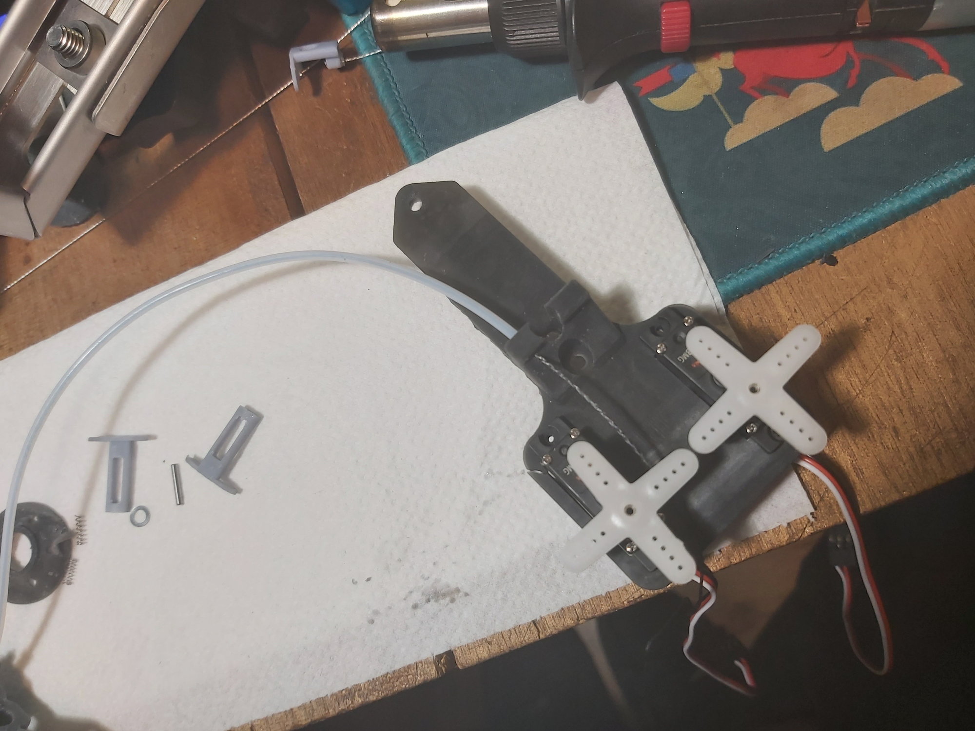
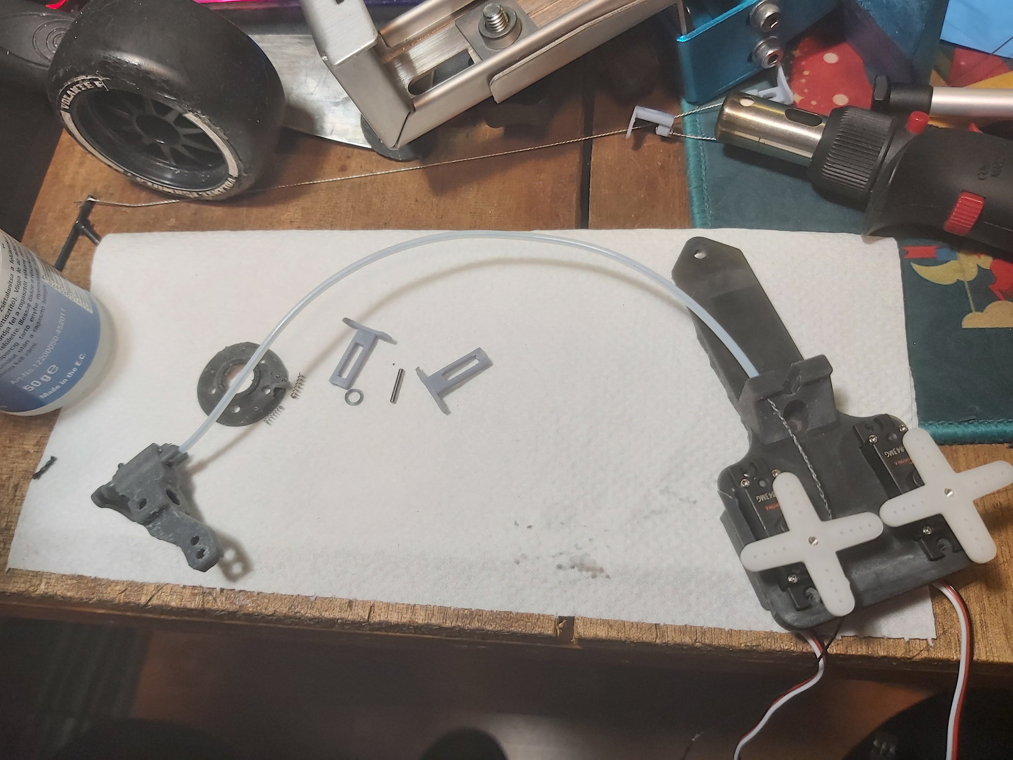
Okay, so finally my servos arrived. Re-drew the servo plate to fit them( they are too tight, I have to adjust to the elephant feet at the bottom of the print), and revisited the concept of torque transfer from wheel to brake disc. Hence, new disc is printed what I managed to mess up, so another batch is ongoing... I am getting there. I also changed the braided steel wire to braided fishing line. They will never tear, but they have better shape conformity, than the cable, making the servo's life somewhat easier. I still have to create the spring mechanism, to protect the servos.Hopefully by the time the season starts, I can do atleast one test day with the prototype. Ofcourse, I'll make some videos, till then, today's pictures have to suffice.
Last edited by mikeylama; 01-10-2022 at 04:41 AM.
12-07-2021, 07:04 AM
#29
Hi, Yes, sorry, I vanished a bit, but I did not abandoned the project, I pinky swear.
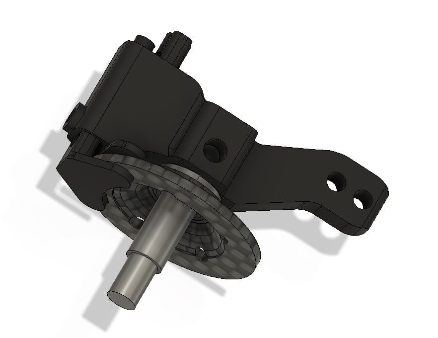
I ran into printing difficulties, namingly I could not get the parts to print out true, the brake disc became warped, even tho I left it on the print bed for curing (resin printing). If I managed to print it out true, the very first braking attempt broke it apart. No surprise, 1mm hardened resin is not a tough material.
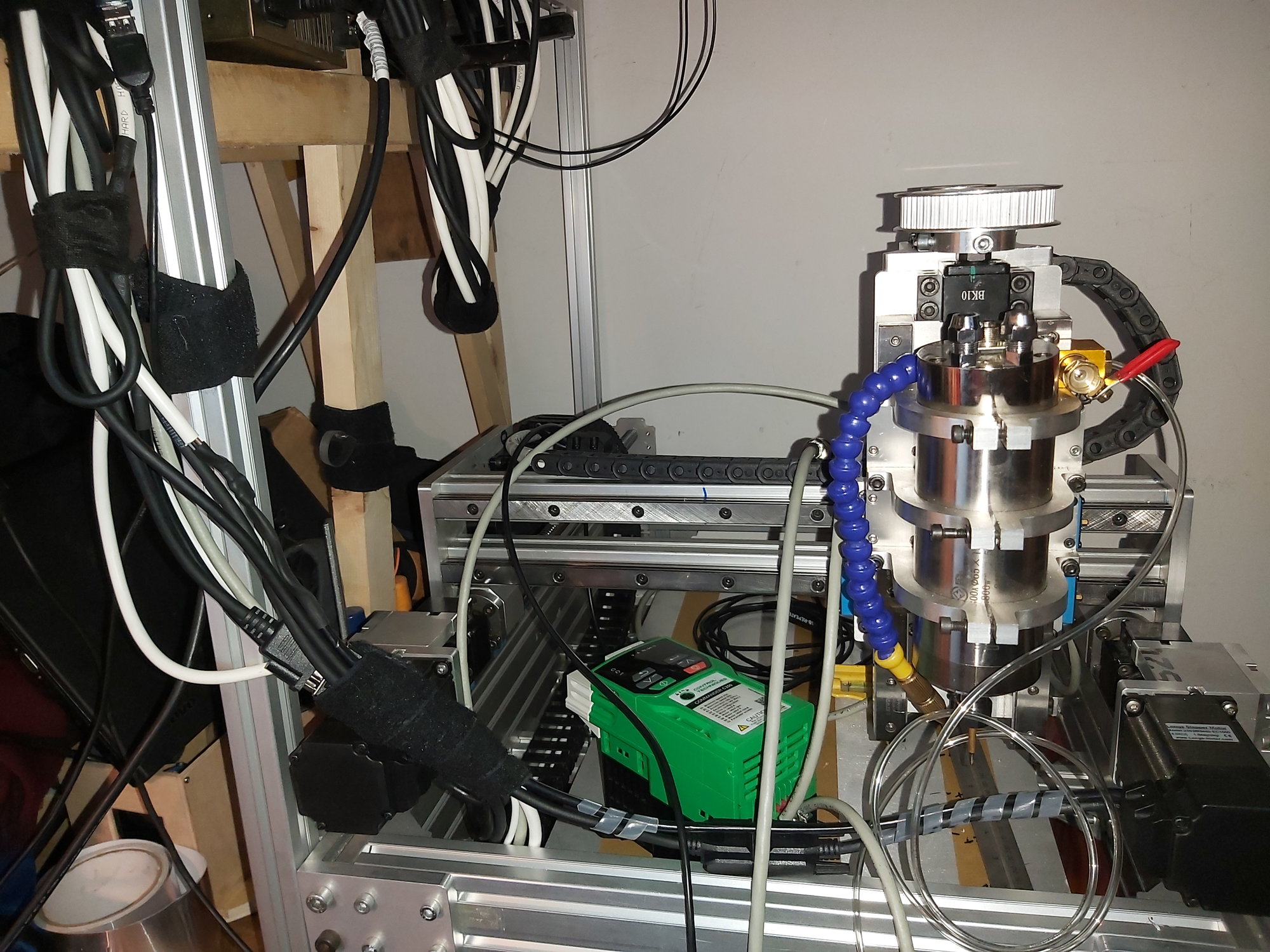
So, the current status is the CAD pic bellow. With the above issues, I had to halt the project, until my cnc router/mill is finished. The first movements are done,but I still need about 20-40 hours of man hour on it to begin testing phase, and then I can start experimenting. The issue is, noone will take the request of milling my parts out of plastic/ cf, so I have to do it myself. So, I started to uild my own CNC. Should I reach prodution with this project, the parts will be injection molded, for what again I need my cnc router/mill to create the injection tools.Not cheap, and certainly not easy, but this is a hobby, and I like to learn
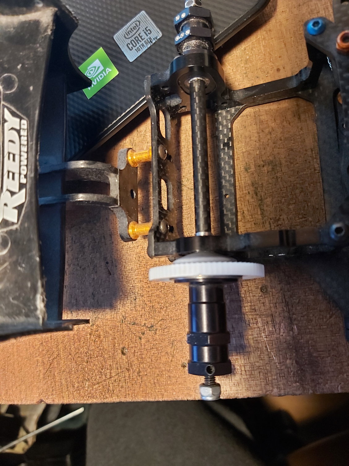
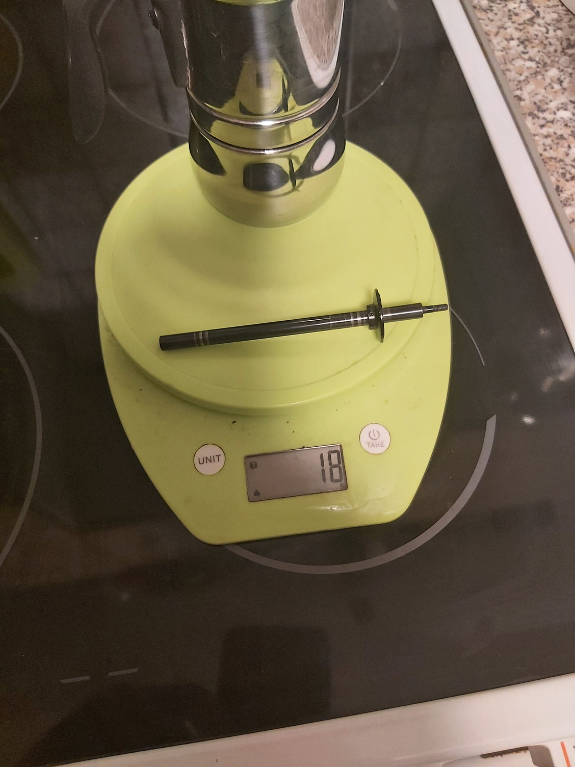
Meanwhile, ultralight rear axle prototype assembly anyone? The durability will not be as crazy as the steel rear shaft, but surely will be stronger, then the cross drilled rod, that the OEM option part consist of. Structural rigidity of the pipe is higher then the rod, so this shall help as well. Also, I did not drill through the tube, but I used bonding agent to fix the plate on. If the tests ( forwhat I have no idea when will I have time) goes smooth, then I MAY commercialise this rear shaft, on a reasonable price. For that, I have to exchange the 3d printed parts to parts cut out from a solid plastic rod. aluminium is too strong, an rather heavy (2.4kg/dm3) over say Polyamid (PA66GF30 1.37kg/dm3) and it's a LOT more durable, then what it has to be.
Sorry, this was quite an excursion into offtopic land. The front brake assembly project is ongoing, but I still have to hit different milestones in order to realize it.

CF woven rear shaft prototype
steel rear shaft
I ran into printing difficulties, namingly I could not get the parts to print out true, the brake disc became warped, even tho I left it on the print bed for curing (resin printing). If I managed to print it out true, the very first braking attempt broke it apart. No surprise, 1mm hardened resin is not a tough material.
So, the current status is the CAD pic bellow. With the above issues, I had to halt the project, until my cnc router/mill is finished. The first movements are done,but I still need about 20-40 hours of man hour on it to begin testing phase, and then I can start experimenting. The issue is, noone will take the request of milling my parts out of plastic/ cf, so I have to do it myself. So, I started to uild my own CNC. Should I reach prodution with this project, the parts will be injection molded, for what again I need my cnc router/mill to create the injection tools.Not cheap, and certainly not easy, but this is a hobby, and I like to learn
Meanwhile, ultralight rear axle prototype assembly anyone? The durability will not be as crazy as the steel rear shaft, but surely will be stronger, then the cross drilled rod, that the OEM option part consist of. Structural rigidity of the pipe is higher then the rod, so this shall help as well. Also, I did not drill through the tube, but I used bonding agent to fix the plate on. If the tests ( forwhat I have no idea when will I have time) goes smooth, then I MAY commercialise this rear shaft, on a reasonable price. For that, I have to exchange the 3d printed parts to parts cut out from a solid plastic rod. aluminium is too strong, an rather heavy (2.4kg/dm3) over say Polyamid (PA66GF30 1.37kg/dm3) and it's a LOT more durable, then what it has to be.
Sorry, this was quite an excursion into offtopic land. The front brake assembly project is ongoing, but I still have to hit different milestones in order to realize it.
CF woven rear shaft prototype
steel rear shaft
Last edited by mikeylama; 12-07-2021 at 07:36 AM.
12-07-2021, 01:44 PM
#30
Tech Rookie
Would it be possible to make a drum style brake where the �drum� is just the wheel?