


 17Likes
Losi Tenacity SCT Thread
 12-17-2018, 09:46 AM
#61
Said footage of mud running. Finally got this thing on a track!! Stoked with how well it did.
 12-17-2018, 01:30 PM
#62

Are people having trouble with heat? I can't get through a single pack without overheating. I thought the stock motor and ESC were perhaps not good enough, but even with my Tenshock motor (rated at 2000 watts peak, 3400kv) I was way over temps within 5-10 min. That motor is quite powerful so I suspect the issue is gearing.
Does anyone have a motor/esc combo that is running cool enough for say, 2-3 back-to-back packs? If so, can you share your setup and how it is performing?
I prefer 3 and 4s in general (most of my trucks run those) so dropping to 2s is not appealing. I tried to fit a smaller pinion but 12 is about the minimum so far without modding the motor mount. I was originally running the Tenacity MT tires which are relatively large (5 inches) but I have dropped down to slightly smaller Mashers 2.8.
Thanks!
12-17-2018, 05:17 PM
#64
You could also think of them as smaller diameter (than standard) 1/8th scale motors.
12-19-2018, 10:52 AM
#66
Tech Addict
iTrader: (19)
Let's say, hypothetically, I was set on the idea of jamming a 40-42mm can motor into this chassis. How would I go about doing so?
I see two potential paths:
1. drill some new holes/slots in the motor mount so the motor moves up just a few millimeters (with the stock holes, the larger can motor touches the chassis). Problem with this is that there's very little open space on the stock motor mount to drill any new holes.
2. Lift the entire motor mount+center diff assembly by 2-3 millimeters. To do this, I'd cut out some lexan or plastic in the appropriate shape, so all touchpoints from the center diff and motor to the chassis are all elevated a bit. That would get the motor high enough up that it would no longer touch the chassis. Challenges are: 1) this would change the driveshaft angle slightly. 2) this would weaken some of the attachment points between the mount and the chassis (in stock form, they are somewhat 'keyed' with a raised circular edge that mates with the mount).
Any thoughts from folks on how to make room for a larger can motor? I know the "right" answer is to get a longer can 36mm motor but I've got the 42mm motor and I am going to use it.
Thanks in advance.
12-19-2018, 11:44 AM
#67
Let's say, hypothetically, I was set on the idea of jamming a 40-42mm can motor into this chassis. How would I go about doing so?
I see two potential paths:
1. drill some new holes/slots in the motor mount so the motor moves up just a few millimeters (with the stock holes, the larger can motor touches the chassis). Problem with this is that there's very little open space on the stock motor mount to drill any new holes.
2. Lift the entire motor mount+center diff assembly by 2-3 millimeters. To do this, I'd cut out some lexan or plastic in the appropriate shape, so all touchpoints from the center diff and motor to the chassis are all elevated a bit. That would get the motor high enough up that it would no longer touch the chassis. Challenges are: 1) this would change the driveshaft angle slightly. 2) this would weaken some of the attachment points between the mount and the chassis (in stock form, they are somewhat 'keyed' with a raised circular edge that mates with the mount).
Any thoughts from folks on how to make room for a larger can motor? I know the "right" answer is to get a longer can 36mm motor but I've got the 42mm motor and I am going to use it.
Thanks in advance.
I see two potential paths:
1. drill some new holes/slots in the motor mount so the motor moves up just a few millimeters (with the stock holes, the larger can motor touches the chassis). Problem with this is that there's very little open space on the stock motor mount to drill any new holes.
2. Lift the entire motor mount+center diff assembly by 2-3 millimeters. To do this, I'd cut out some lexan or plastic in the appropriate shape, so all touchpoints from the center diff and motor to the chassis are all elevated a bit. That would get the motor high enough up that it would no longer touch the chassis. Challenges are: 1) this would change the driveshaft angle slightly. 2) this would weaken some of the attachment points between the mount and the chassis (in stock form, they are somewhat 'keyed' with a raised circular edge that mates with the mount).
Any thoughts from folks on how to make room for a larger can motor? I know the "right" answer is to get a longer can 36mm motor but I've got the 42mm motor and I am going to use it.
Thanks in advance.
Regarding #1, as you say, there's not really room in the motor mount to do this very well.
Regarding #2, I would not advise that because then the lengthwise chassis braces would be bent at an angle.
So I thought of a third idea and whether it will work for you depends on what motor you have. If the front endbell of the motor is removable, drill a new pair of motor mount holes offset from the others a little bit to raise the center of the motor. That is, position them so the motor shaft is no longer centered between the two new holes. Looks like you only need to move them about 2MM. Drill them in a parts of the endbell that doesn't already have a pair of holes.
I've done the "new holes" thing in a couple of older Castle 15 series motors. Not to offset them but because they come with 3MM holes and I wanted to use 4MM screws to match what a Losi 8 2.0 motor mount is designed for. I suppose I could have just enlarged and re-tapped two of the existing holes in the Castle endbell, but I wanted to leave them alone. You need the correct size drill bit (2.5MM for a 3MM screw) and a 3MM tap, but this is probably easier overall than trying to modify the motor mount itself. Assuming, of course, the endbell is removable from the motor. I would not try this otherwise.
You can probably find a 3MM tap lots of places. If you can't conveniently find a 2.5MM drill, use the wire gauge drill closest in size. Don't try it with a fractional drill or you might not get enough bite for the tap for the screws to hold the motor in. If you don't want to do this yourself, a local Mom&Pop machine shop would probably do it for $25 or less.
The advantage of this approach is that you don't need to do anything to the truck, and the change to the motor makes no difference for any other application.
12-20-2018, 09:08 AM
#68
Tech Addict
iTrader: (19)
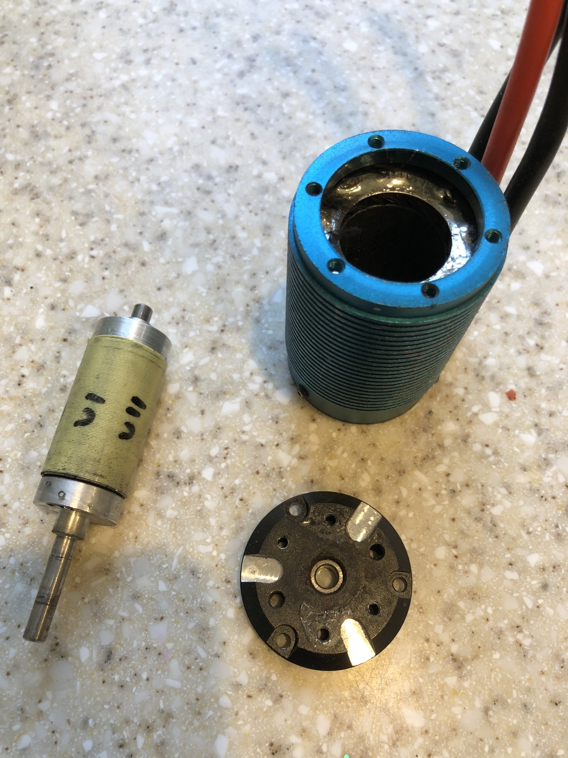
Ta_man, what a great idea! Thanks for taking the time to write this up and explain it to me.
I am going with your idea. I have ordered a new motor faceplate (cheap insurance for a nice motor) and I have started planning the surgery.
I don�t fully recognize all the terms you used (wire gauge drill, fractional drill) but I�ll google them. I have normal tools and this seems straightforward.
Question: as you can see the mfg didn�t leave much unused space. Do you think I can drill through those shiny exposed divots? That would give me a nice clean slice of space. Since this is a custom job I can even flip the screw so the head is inside the motor and use a nut on the outside. That way the lack of depth in the divot might not be an issue.
Thanks again!!
12-20-2018, 12:25 PM
#69
aaaand my Tenacity-T is now an 1/8 buggy. 

12-20-2018, 02:08 PM
#70
Ta_man, what a great idea! Thanks for taking the time to write this up and explain it to me.
I am going with your idea. I have ordered a new motor faceplate (cheap insurance for a nice motor) and I have started planning the surgery.
I don’t fully recognize all the terms you used (wire gauge drill, fractional drill) but I’ll google them. I have normal tools and this seems straightforward.
Question: as you can see the mfg didn’t leave much unused space. Do you think I can drill through those shiny exposed divots? That would give me a nice clean slice of space. Since this is a custom job I can even flip the screw so the head is inside the motor and use a nut on the outside. That way the lack of depth in the divot might not be an issue.
Thanks again!!
If it is a 42MM Motor you might not need to get into the outer ring or the shiny stuff.
14MM Motor means 21mm from shaft center to edge, Normal screw spacing is 15MM so 12.5MM from shaft center to mounting hole center another 1.5MM for the outer half of the screw hole gives you 14MM from shaft center to edge of screw hole. Move it down 2MM gives 16MM leaving you another 5MM from outer edge of screw hole to outer edge of motor. Might not be enough room for the screw to clear the run. If you are close see what happens if you only move the hole down 1.5MM.
Also, the screw only needs to go in the thickness of the endbell, any more was hanging in the air.
I just checked one of my Castle 15 series motors and it looks like I could only move a 3MM hole about 1.5MM before the screw would hit the inner edge of the front mount ring. But if I needed to move it 2MM, I would do it and just use a short enough screw that it wouldn't bottom out on the mounting face.
01-21-2019, 08:55 AM
#72
Not really a mod per se. The diffs are built for 4 spiders gears but some batches only shipped with 2. I heard it was to cut down on noise. You can pull your diffs and check before you run out and buy the gears.
01-21-2019, 11:21 PM
#75
Unfortunately they come in full sets. But you can buy 1 set of tenacity diff gears and I think 1 set of Ten T gears which will get you the 6 total spider gears. (As opposed to buying 2 sets of tenacity gears which ends you up with 8 spider gears)