


Project: Team Kassanova K2v2 (2wd buggy)
 12-10-2010, 09:44 PM
#61

Sounds good. I am liking it so far alot. Going to be for those High bite tracks and for one to go fast. I like the Lay down shocks. My buddy has them on his 4wd x11 predator I think. But they look great and will function better in certain conditions.. keep up the work. Cant wait to see a finished product and maybe bring advice to the table. 

 12-13-2010, 02:40 PM
#62
Yea I'm specifically designing and building this buggy for my local track which is high bite. Thanks open to any advice.
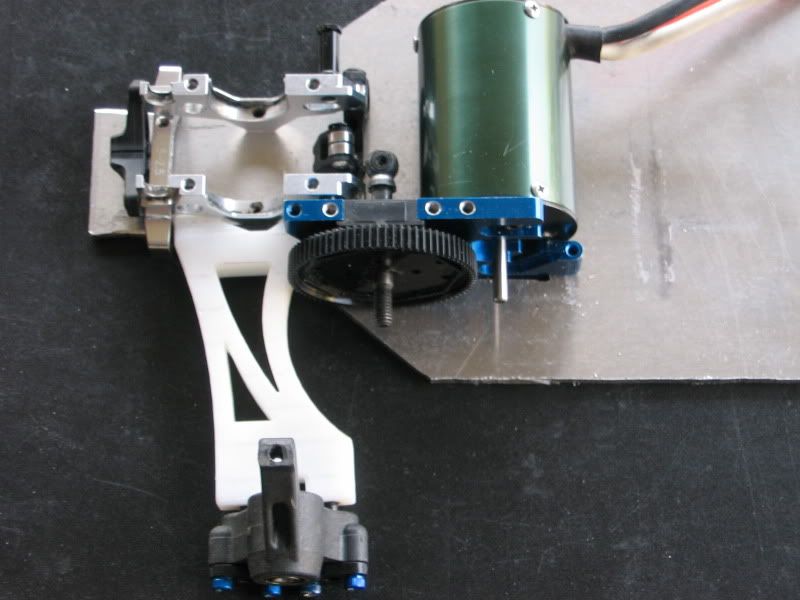
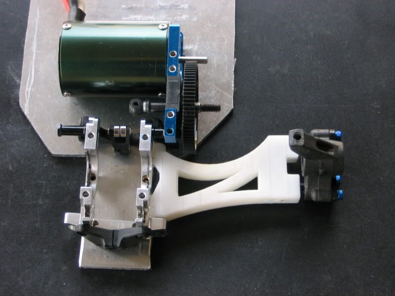
A mock rear a-arm was printed today so see if everything fits. Their are a few small changes I need to make with the spacing and sizes of the holes but for the most part it turned out great. The finish surface isn't the smoothest in some spots but with a slight amount of sanding it became smooth. I'm also think I will make the center section of the a-arm thicker since I don't think its quiet wide enough.
I'm going to get a final drawing done of the rear a-arms and get the front a-arm design ready for printing too. A nice feature about the a-arms are they can be used on either the right or left so I don't have to have as many spares.
Last edited by eds24; 03-27-2011 at 11:39 AM.
12-14-2010, 07:08 PM
#63
Even though I was supposed to be studying for a math test today I decided to dedicate sometime to the project.
I knew when I started this project that I would have to find some way to put a slipper clutch on this since their is no factory slipper clutch for the E4.. though why would their its an on-road car. Since this is an off-road car it has to have a slipper clutch.
After looking at different factory slipper clutches I realized I would have to design and build my own. I attempted to make one a couple months ago out of a cut up tc3 aluminum center drive shaft. Everything was going good until I had to thread the threaded rod into the aluminum piece. I used a drill to thread the threaded rod in the aluminum but soon realized the hole was too small. The threaded rod ended up breaking off in the aluminum shaft and the hours of filing went to waste
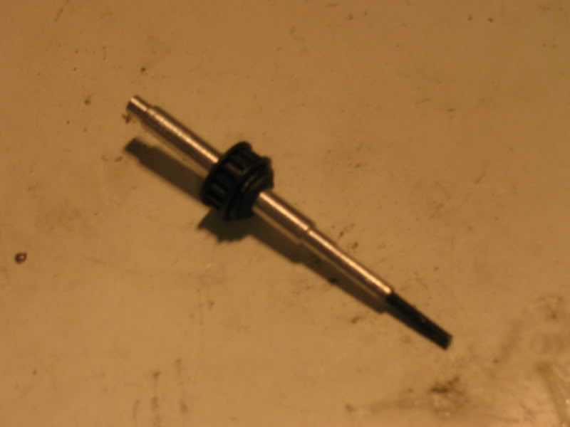
Today I successfully made a slipper clutch out of a aluminum rod I picked up at Home Depot. I spent a few hours "latheing" it down in certain spots by throwing it into the drill press and using a file. I also had to file flat spots in it so the B4 slipper plates would fit.
Overall it came out awesome and this has to be one of the nicest pieces I have ever made. Now I won't have to worry about this project coming to dead end becuase their is no slipper clutch.
(I still have to file the motor hole in the chassis)
I knew when I started this project that I would have to find some way to put a slipper clutch on this since their is no factory slipper clutch for the E4.. though why would their its an on-road car. Since this is an off-road car it has to have a slipper clutch.
After looking at different factory slipper clutches I realized I would have to design and build my own. I attempted to make one a couple months ago out of a cut up tc3 aluminum center drive shaft. Everything was going good until I had to thread the threaded rod into the aluminum piece. I used a drill to thread the threaded rod in the aluminum but soon realized the hole was too small. The threaded rod ended up breaking off in the aluminum shaft and the hours of filing went to waste
Today I successfully made a slipper clutch out of a aluminum rod I picked up at Home Depot. I spent a few hours "latheing" it down in certain spots by throwing it into the drill press and using a file. I also had to file flat spots in it so the B4 slipper plates would fit.
Overall it came out awesome and this has to be one of the nicest pieces I have ever made. Now I won't have to worry about this project coming to dead end becuase their is no slipper clutch.
(I still have to file the motor hole in the chassis)
Last edited by eds24; 03-27-2011 at 11:40 AM.
01-01-2011, 10:31 PM
#65
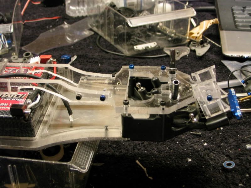
The winter break has given me an opportunity to get some pretty substantial progress made. I also received the parts I need for the rest of the build.
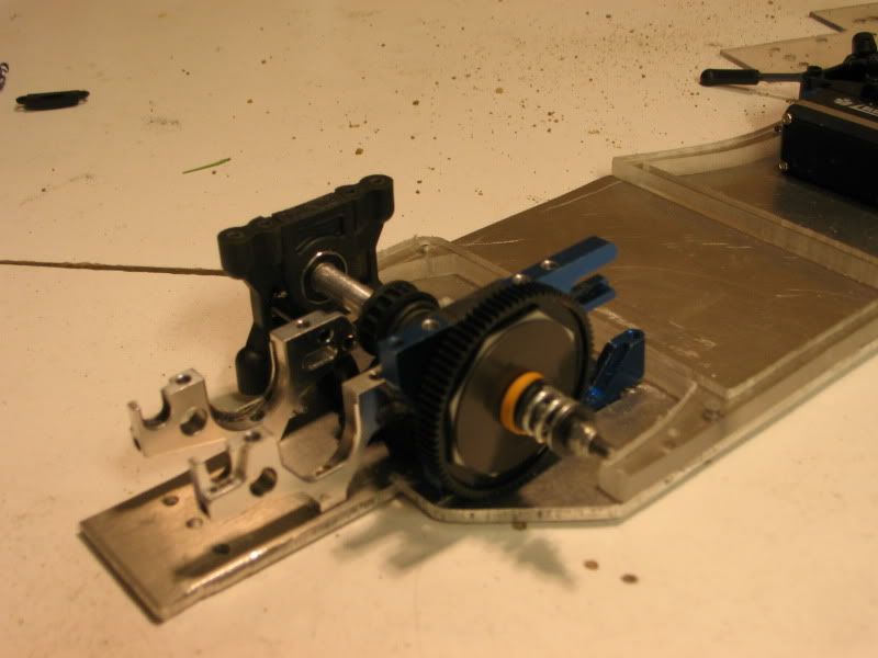
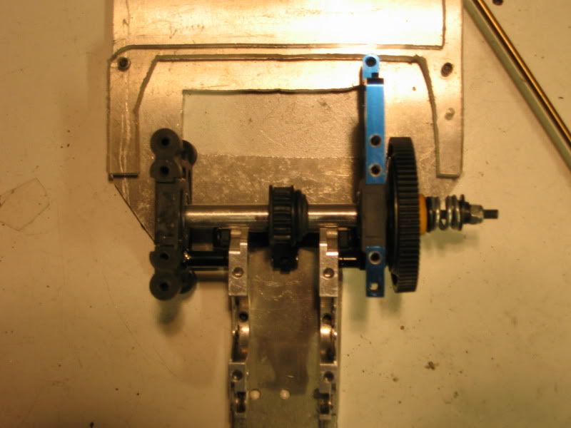
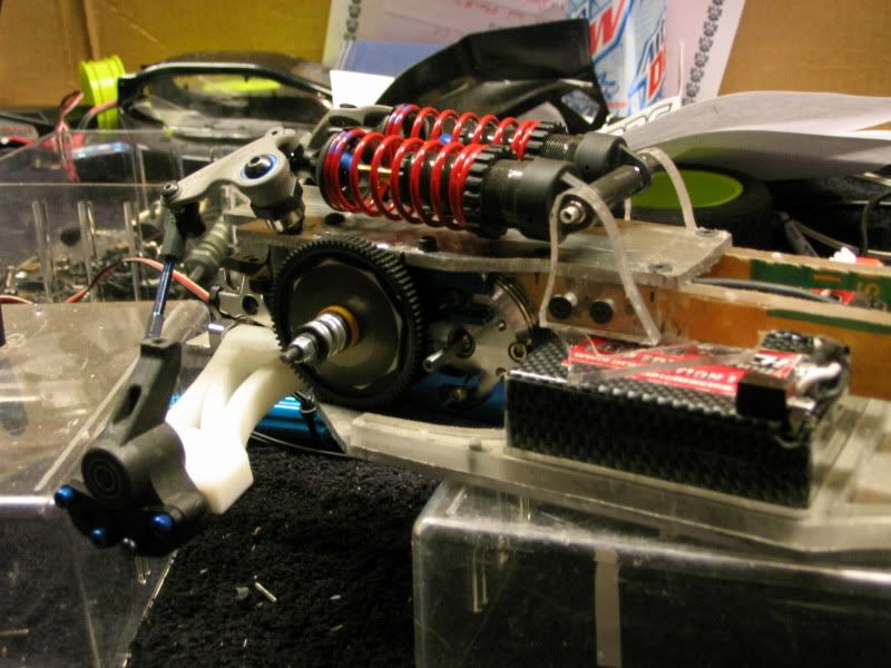
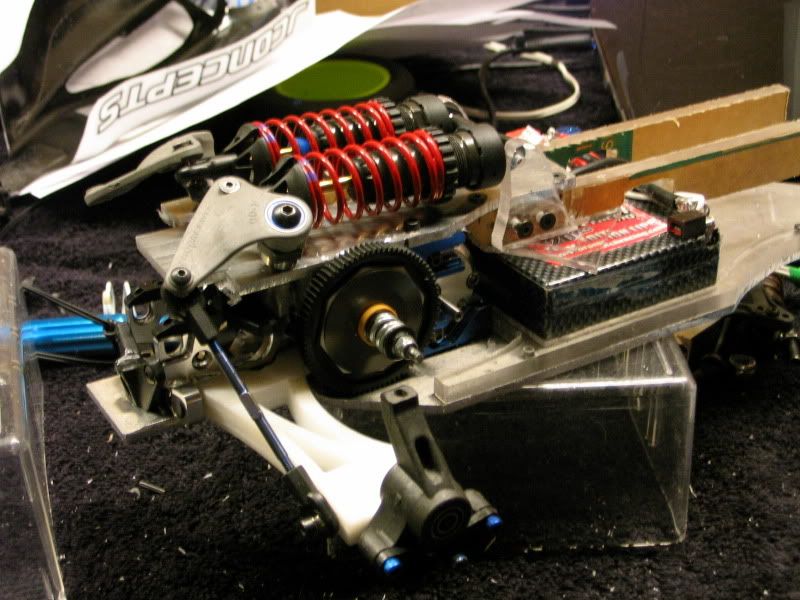
I started by building and installing the E4 diff. This required me to cut a hole under the diff so it can sit fully. While I was at it fully mounted the motor mount and filed the motor slot in the chassis. I currently don't have the diff in the buggy so that I can test the suspension (The a-arm doesn't work with the diff atm)
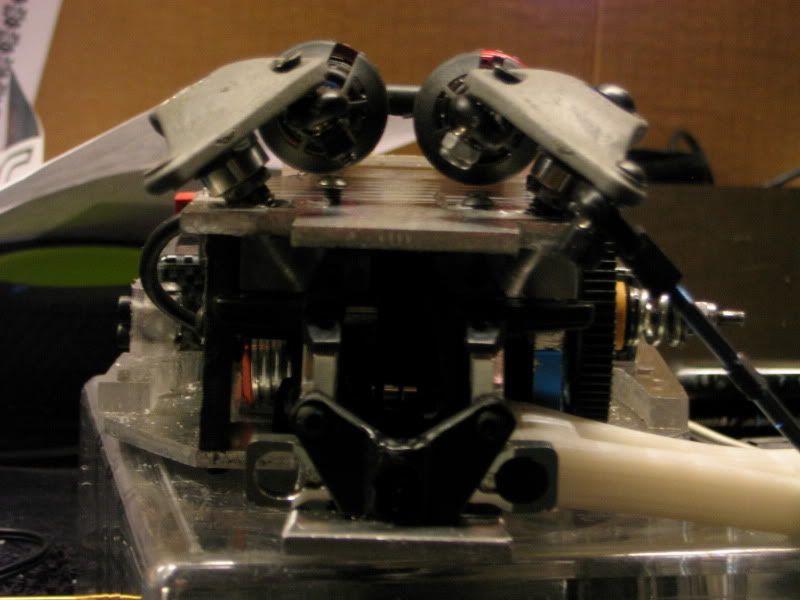
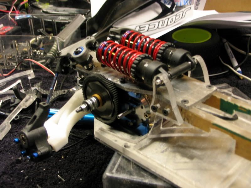
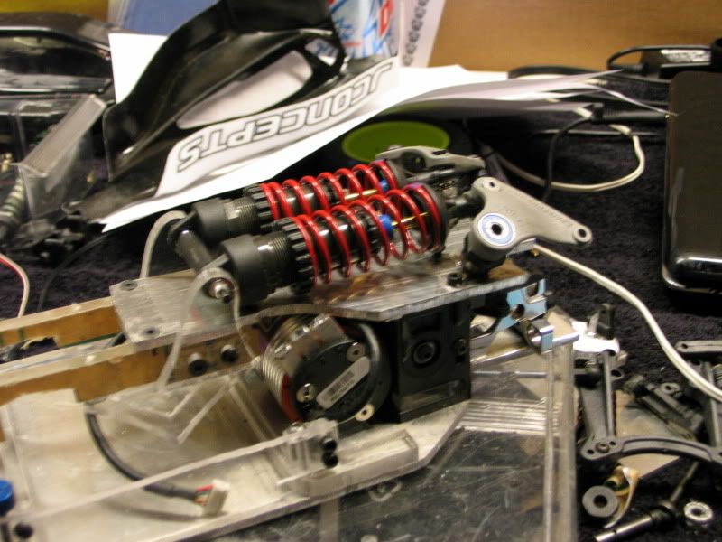
After I got the diff installed and started working on trying to figure out a way to mount the rocker posts for the laydown suspension. I decided on making a custom mount out of 3/8" lexan. With my drill press this was a much easier task then it has been in the past with my hand drill. I measured the angle of the rocker posts on my Evo8 project (Slayer buggy) and matched it. I had to cut a channel in the center of the mount for the belt to go thru.
After I got that all mounted up I moved on to cutting the upper chassis out of 1/8" aluminum. At this point I took a break and decided to do some electrical work so that I could make the center upper chassis.
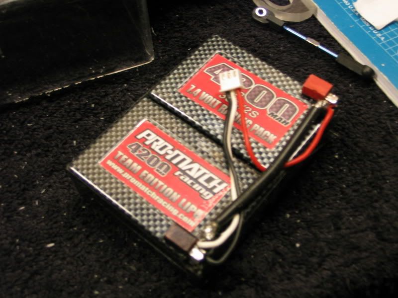
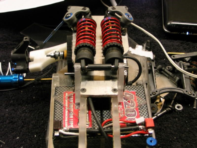
My Promatch Saddle battery packs don't have built in bullet connectors but I like how clean bullet connectors are. So I came up with a solution using Dean connections. I will let a picture speak for this modification.
I also used packaging tape to tape the saddles together to make it easier to slide the battery in the buggy.
After I cut the battery done I was able to cut the center part of the upper deck out of 1/4" lexan. I had to cut slots out of the lexan for the deans to pass thru as the battery slides into place. I then got the shocks mounts made and mounted them. I made it so I can easily adjust the shocks forward and backwards.
Anyway... the pictures explain everything much more clearly. I haven't been able to take all the paper off of the Lexan becuase I still need to cut down the center upper chassis. I think it will look good once all the paper is off.
Remember all the aluminum plate parts will be replaced with Carbon down the road.
On to the pics...
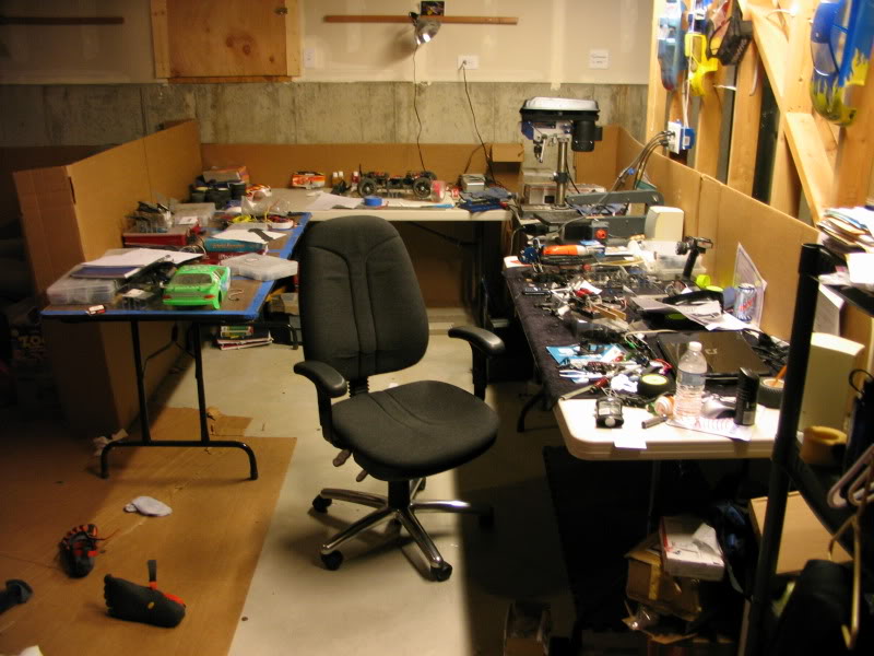
Oh and a quick picture of the workshop in its current state haha.
I started by building and installing the E4 diff. This required me to cut a hole under the diff so it can sit fully. While I was at it fully mounted the motor mount and filed the motor slot in the chassis. I currently don't have the diff in the buggy so that I can test the suspension (The a-arm doesn't work with the diff atm)
After I got the diff installed and started working on trying to figure out a way to mount the rocker posts for the laydown suspension. I decided on making a custom mount out of 3/8" lexan. With my drill press this was a much easier task then it has been in the past with my hand drill. I measured the angle of the rocker posts on my Evo8 project (Slayer buggy) and matched it. I had to cut a channel in the center of the mount for the belt to go thru.
After I got that all mounted up I moved on to cutting the upper chassis out of 1/8" aluminum. At this point I took a break and decided to do some electrical work so that I could make the center upper chassis.
My Promatch Saddle battery packs don't have built in bullet connectors but I like how clean bullet connectors are. So I came up with a solution using Dean connections. I will let a picture speak for this modification.
I also used packaging tape to tape the saddles together to make it easier to slide the battery in the buggy.
After I cut the battery done I was able to cut the center part of the upper deck out of 1/4" lexan. I had to cut slots out of the lexan for the deans to pass thru as the battery slides into place. I then got the shocks mounts made and mounted them. I made it so I can easily adjust the shocks forward and backwards.
Anyway... the pictures explain everything much more clearly. I haven't been able to take all the paper off of the Lexan becuase I still need to cut down the center upper chassis. I think it will look good once all the paper is off.
Remember all the aluminum plate parts will be replaced with Carbon down the road.
On to the pics...
Oh and a quick picture of the workshop in its current state haha.
01-01-2011, 10:38 PM
#66
The winter break has given me an opportunity to get some pretty substantial progress made. I also received the parts I need for the rest of the build.
I started by building and installing the E4 diff. This required me to cut a hole under the diff so it can sit fully. While I was at it fully mounted the motor mount and filed the motor slot in the chassis. I currently don't have the diff in the buggy so that I can test the suspension (The a-arm doesn't work with the diff atm)
After I got the diff installed and started working on trying to figure out a way to mount the rocker posts for the laydown suspension. I decided on making a custom mount out of 3/8" lexan. With my drill press this was a much easier task then it has been in the past with my hand drill. I measured the angle of the rocker posts on my Evo8 project (Slayer buggy) and matched it. I had to cut a channel in the center of the mount for the belt to go thru.
After I got that all mounted up I moved on to cutting the upper chassis out of 1/8" aluminum. At this point I took a break and decided to do some electrical work so that I could make the center upper chassis.
My Promatch Saddle battery packs don't have built in bullet connectors but I like how clean bullet connectors are. So I came up with a solution using Dean connections. I will let a picture speak for this modification.
I also used packaging tape to tape the saddles together to make it easier to slide the battery in the buggy.
After I cut the battery done I was able to cut the center part of the upper deck out of 1/4" lexan. I had to cut slots out of the lexan for the deans to pass thru as the battery slides into place. I then got the shocks mounts made and mounted them. I made it so I can easily adjust the shocks forward and backwards.
Anyway... the pictures explain everything much more clearly. I haven't been able to take all the paper off of the Lexan becuase I still need to cut down the center upper chassis. I think it will look good once all the paper is off.
Remember all the aluminum plate parts will be replaced with Carbon down the road.
On to the pics...
Oh and a quick picture of the workshop in its current state haha.
nice vibrams
 lol
01-02-2011, 08:48 AM
lol
01-02-2011, 08:48 AM
#68
i like your project, keep up the good work. if you can provide me with 2d dxf files i can cut your carbon stuff for you at a decent price, having all of your mount holes in precision locations will make a HUGE difference.
01-02-2011, 05:39 PM
#69
LetsDrive!: Thanks haha gotta love the fivefingers
Pyscob4: Thanks man. As far as the FDR goes.. I have been messing around with a calculator some.. and I figure with 81 spur and between a 20-23 pinion I will get a FDR in the range of 7-8. This is the about the range people recommend for a B4 with a 13.5 motor.
Mantis: Thanks I might have to contact you in a few weeks about getting a quote and stuff some precision parts would be nice.
Came up with a deadline for the aluminum proto of this project.
At the latest...January 21st
Last edited by eds24; 01-03-2011 at 02:37 PM.
01-02-2011, 06:43 PM
#70
Why such a High Spur?? I would go with a 72-78 tooth spur and that way there is more play around, but I could be wrong too. 7-8 still is a good FDR.. Just dont like the big spurs all the time.
Looks like you got her going well, I checked out your site. Some pretty Cool stuff you got there..
thanks for the quick responses and great Photos!!! Awesome Job and Happy Holidays.
Looks like you got her going well, I checked out your site. Some pretty Cool stuff you got there..
thanks for the quick responses and great Photos!!! Awesome Job and Happy Holidays.
01-02-2011, 11:10 PM
#72
Tech Initiate
Interesting project. I run my mid motor X6 at MHOR quite often, it runs great. As far as the Losi boys, I've tried to talk Dustin into it, but he's not super pumped about it, Matt would probably try it later on when they get a good setup established on the rear motor. I run Shumacher big bores at MHOR and like the 4 hole pistons with 35wt in the front and 32.5 wt in the rear, not sure if that will help with your inboard shock contraption, but there ya go. Is it going to be ready for the Rumble race? I'll be going to that race for sure, just booked my plane ticket. I'll be pitted next to Dustin, Matt and Kody, if it's ready I'd like to look at it. Have a good one.
01-03-2011, 02:32 PM
#73
Why such a High Spur?? I would go with a 72-78 tooth spur and that way there is more play around, but I could be wrong too. 7-8 still is a good FDR.. Just dont like the big spurs all the time.
Looks like you got her going well, I checked out your site. Some pretty Cool stuff you got there..
thanks for the quick responses and great Photos!!! Awesome Job and Happy Holidays.
Looks like you got her going well, I checked out your site. Some pretty Cool stuff you got there..
thanks for the quick responses and great Photos!!! Awesome Job and Happy Holidays.
You'll just have to wait and see haha
Interesting project. I run my mid motor X6 at MHOR quite often, it runs great. As far as the Losi boys, I've tried to talk Dustin into it, but he's not super pumped about it, Matt would probably try it later on when they get a good setup established on the rear motor. I run Shumacher big bores at MHOR and like the 4 hole pistons with 35wt in the front and 32.5 wt in the rear, not sure if that will help with your inboard shock contraption, but there ya go. Is it going to be ready for the Rumble race? I'll be going to that race for sure, just booked my plane ticket. I'll be pitted next to Dustin, Matt and Kody, if it's ready I'd like to look at it. Have a good one.
Thats good to hear that a mid motor buggy runs well at MHOR. Yea, thats what I have heard is that they are trying to get a set-up dialed for the rear motor. I was sorta trying to figure out what oil would be good.. I think you gave me a good starting point thanks.
Yea its going to be ready for the Rumble. I'm definatly planning on running it at the Rumble. It will actually be is "debut" race. I'm just trying to get it done a few weeks before then so i have enough time to test it and work on getting it set-up.
I'm sure it'll be pretty easy to spot.. with inboard suspension and all...and I'll be wearing a t-shirt that says Team Kassanova on it. I'll try and find ya so you can take a look at it.
01-08-2011, 09:04 PM
#74
I've been working on the front end recently. I got the chassis stiffeners trimmed and took the paper off of them. I believe with this design their might be a possibility of having adjustable chassis flex.. by adding or taking away vertical posts in between the two vertical plates.
I also got the front upper chassis done. I got a B4 steering rack mounted on it. I was trying to decide between the Gt2 steering rack and B4 steering rack. I decided on the B4 rack because it seems to me that it would create better steering geometry since the width of the buggy will be far less then a Gt2. Also got the rocker posts mounted onto this upper deck.
I also mounted some risers to connect the bulkhead to the upper chassis. They extend past the upper chassis because on top of it will be a bulkhead for the upper a-arms. I have to have upper a-arms because of the pivot ball suspension.
(I obviously have alot of countersinking to do... my favorite..") )
)
Next up I will be working on mounting the front shocks and rockers. I got the final Solidworks drawing of the Front and Rear a-arms ready for 3d printing and I should have those either monday or tuesday.
13 days till until aluminum prototype deadline!
I also got the front upper chassis done. I got a B4 steering rack mounted on it. I was trying to decide between the Gt2 steering rack and B4 steering rack. I decided on the B4 rack because it seems to me that it would create better steering geometry since the width of the buggy will be far less then a Gt2. Also got the rocker posts mounted onto this upper deck.
I also mounted some risers to connect the bulkhead to the upper chassis. They extend past the upper chassis because on top of it will be a bulkhead for the upper a-arms. I have to have upper a-arms because of the pivot ball suspension.
(I obviously have alot of countersinking to do... my favorite..
)Next up I will be working on mounting the front shocks and rockers. I got the final Solidworks drawing of the Front and Rear a-arms ready for 3d printing and I should have those either monday or tuesday.
13 days till until aluminum prototype deadline!
Last edited by eds24; 03-27-2011 at 11:42 AM.
01-08-2011, 09:38 PM
#75
I've been working on the front end recently. I got the chassis stiffeners trimmed and took the paper off of them. I believe with this design their might be a possibility of having adjustable chassis flex.. by adding or taking away vertical posts in between the two vertical plates.
I also got the front upper chassis done. I got a B4 steering rack mounted on it. I was trying to decide between the Gt2 steering rack and B4 steering rack. I decided on the B4 rack because it seems to me that it would create better steering geometry since the width of the buggy will be far less then a Gt2. Also got the rocker posts mounted onto this upper deck.
I also mounted some risers to connect the bulkhead to the upper chassis. They extend past the upper chassis because on top of it will be a bulkhead for the upper a-arms. I have to have upper a-arms because of the pivot ball suspension.
(I obviously have alot of countersinking to do... my favorite..)
Next up I will be working on mounting the front shocks and rockers. I got the final Solidworks drawing of the Front and Rear a-arms ready for 3d printing and I should have those either monday or tuesday.
13 days till until aluminum prototype deadline!
I also got the front upper chassis done. I got a B4 steering rack mounted on it. I was trying to decide between the Gt2 steering rack and B4 steering rack. I decided on the B4 rack because it seems to me that it would create better steering geometry since the width of the buggy will be far less then a Gt2. Also got the rocker posts mounted onto this upper deck.
I also mounted some risers to connect the bulkhead to the upper chassis. They extend past the upper chassis because on top of it will be a bulkhead for the upper a-arms. I have to have upper a-arms because of the pivot ball suspension.
(I obviously have alot of countersinking to do... my favorite..
)Next up I will be working on mounting the front shocks and rockers. I got the final Solidworks drawing of the Front and Rear a-arms ready for 3d printing and I should have those either monday or tuesday.
13 days till until aluminum prototype deadline!
Awesome Job,. It is coming along great, and is looking awesome every post. keep up the work and let us know how she goes....
If you find some #s or info or the specs on the buggy that would be great. Thanks again for the time posting pics, and sharing the info with us!

