


 244Likes
Rethinking 2wd Buggy Design
 01-04-2018, 12:28 AM
#91
In general for 3D modeling you would like as many large objects present as possible, so a cylinder for the shock would be okay, no need to model threads or springs. All has to do with how accurate of a model you would like, and your computing power, to show how sensitive the components are. Which leads to your second point, which may be true. CFD and subsequent on track testing to correlate the computer model would tell for sure what is actually happening. My initial guess is that it is too small with a Reynolds number that is too high for actual wings to take an affect, which is probably why most all RC’s (even 1/8 scale) have spoilers rather than proper wings. But it would be interesting to see what OP can discover with his project.
But the primary focus of this project is not the aero. Just having fun with the program.
 01-04-2018, 12:35 AM
#92
Are the wheels you are making going to be for those skinny carpet tires? Because looking at the front end of my my TLR car that is the only other way I could see those aero covers lining up where they do.
Additionally, I really don't think you have accounted for how much the wheels flex under load. I think those inner wheel covers are going to rub the wheel.
Finally, if there is ever a small bump where you have slow speed and the bump is not at 90� to the direction of travel (small bump in a corner or in between a left and right corner), I think your a-arm could catch on the tops of the bumps.
01-05-2018, 08:51 PM
#93
Are the wheels you are making going to be for those skinny carpet tires? Because looking at the front end of my my TLR car that is the only other way I could see those aero covers lining up where they do.
Additionally, I really don't think you have accounted for how much the wheels flex under load. I think those inner wheel covers are going to rub the wheel.
Finally, if there is ever a small bump where you have slow speed and the bump is not at 90� to the direction of travel (small bump in a corner or in between a left and right corner), I think your a-arm could catch on the tops of the bumps.
Additionally, I really don't think you have accounted for how much the wheels flex under load. I think those inner wheel covers are going to rub the wheel.
Finally, if there is ever a small bump where you have slow speed and the bump is not at 90� to the direction of travel (small bump in a corner or in between a left and right corner), I think your a-arm could catch on the tops of the bumps.
As for the last comment yes the arms hang low but I am going to be modifying that design when I address the length of the arms. After going over the whole model and working the math I am going to moving out the front shocks on the arms. Right now they are roughly in a slightly lower position of the factory middle hole. I want to move it to the outer hole to compensate for some geometry changes and carpet mindedness. This is going to move the low point out and up a little bit. This should give sufficient clearance.
Yah I know they are low and this was a decision I made to get the CG really low. The best part is if you work out the geometry I am very close to the 22.
My printer parts just showed up so my current focus is on the necessary printer upgrades. I made a test print of the front monocoque and encountered some problems with the Y carriage so I am printing some modified parts right now. I am also going to be making some slight design changes to the monocoque, fixing some problems and incorporating some new ideas. Ill post pics soon.
01-06-2018, 08:22 AM
#94
Tech Apprentice
Maybe I missed it, but have you considered the impact that the tires and wheels will have on airflow? F1 teams spend billions on tiny bits to deal with the disruption caused by the open wheels.
Interesting thread.
Interesting thread.
01-06-2018, 02:22 PM
#95
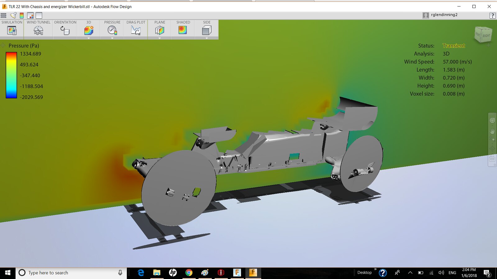
Even though aero isn't the main focus of the project (just one of the pieces of the puzzle) I have been messing around with it to help further develop the chassis as a whole.
The next step in the aero development is to re-design the front arms again because they are having an interesting interaction with the ground and is causing a higher pressure buildup at the front. I think this is causing further issues with the front of the body. In the 3D model there is very little airflow to the font window.
 Buggy 40
You can see here the high pressure build-up at the front which is causing the air to go up and over the front. I am getting very little effect from the front part of the body.
 Buggy 39
Its hard to see in a still picture but all of the airflow is avoiding the high pressure area and travelling above the front of the car. In the picture you can see the slow travelling turbulent air in front of the cab window and down the side.
So I am going to try and relieve that pressure by changing the shape of the front arms. But I want to try and not disturb airflow to the rear arms. I am also thinking of ideas to modify the flow through bulkhead to create more laminar airflow over the hood and front window.
Oh yah the big disks are there as a test to see how the inner wheel disk would act a winglets for the rear arms. I will include more accurate wheels in the next test.
01-08-2018, 07:03 AM
#96

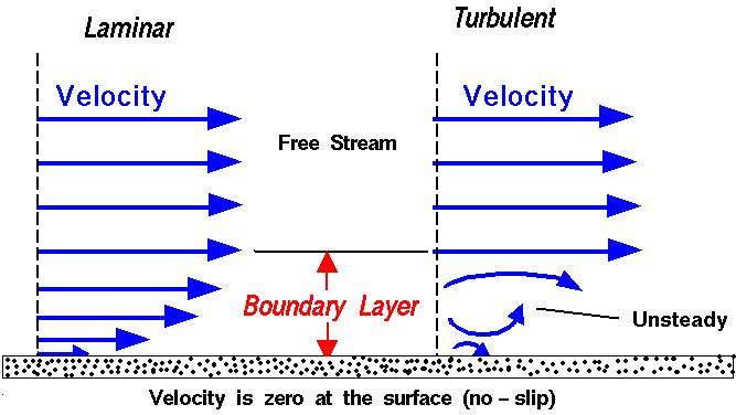
I can't tell in those two screen shots, but in your previous posts it looks like the ground isn't moving with the air in the model. If the car is sitting static and the ground is static, just sending air across those surfaces will be very different than if the car is static and the ground/air are both moving with the same velocity.
The boundary layer formed with the ground will create lower velocity, higher pressure areas at the front of the car like you are seeing.
Just don't want you to spend time trying to fix something that might not be broken.
The boundary layer formed with the ground will create lower velocity, higher pressure areas at the front of the car like you are seeing.
Just don't want you to spend time trying to fix something that might not be broken.
01-08-2018, 08:03 AM
#97
Yeah, you have to have software (and hardware) powerful enough to run the simulation to match what the car is actually doing in the real world.
I just don't think the modelling software can deal with the size of our cars. I think the math behind the programming has been tuned to give accurate information for a full size vehicle, and if you model something way smaller than what the software has been designed for it isn't going to give accurate information.
Also, I know you can only scale up and down so much before the data becomes unreliable. So even modelling the car large enough for the software to give an accurate portrayal of what would happen with a vehicle that shape is not what is gonna happen in the real world with a car of that shape, but the size of a 1/10th scale buggy.
The main thing that dictates the handling is weight distribution and flex characteristics. I just don't see how he is going to get all that right, and clean up the aero. He is making compromises to those things in the name of infinitesimal aero gains.
It's cool that he is trying different things, but I don't think it will make for a car that is faster on track than a current generation car.
01-08-2018, 11:10 AM
#98
Yeah, you have to have software (and hardware) powerful enough to run the simulation to match what the car is actually doing in the real world.
I just don't think the modelling software can deal with the size of our cars. I think the math behind the programming has been tuned to give accurate information for a full size vehicle, and if you model something way smaller than what the software has been designed for it isn't going to give accurate information.
Also, I know you can only scale up and down so much before the data becomes unreliable. So even modelling the car large enough for the software to give an accurate portrayal of what would happen with a vehicle that shape is not what is gonna happen in the real world with a car of that shape, but the size of a 1/10th scale buggy.
The main thing that dictates the handling is weight distribution and flex characteristics. I just don't see how he is going to get all that right, and clean up the aero. He is making compromises to those things in the name of infinitesimal aero gains.
It's cool that he is trying different things, but I don't think it will make for a car that is faster on track than a current generation car.
I just don't think the modelling software can deal with the size of our cars. I think the math behind the programming has been tuned to give accurate information for a full size vehicle, and if you model something way smaller than what the software has been designed for it isn't going to give accurate information.
Also, I know you can only scale up and down so much before the data becomes unreliable. So even modelling the car large enough for the software to give an accurate portrayal of what would happen with a vehicle that shape is not what is gonna happen in the real world with a car of that shape, but the size of a 1/10th scale buggy.
The main thing that dictates the handling is weight distribution and flex characteristics. I just don't see how he is going to get all that right, and clean up the aero. He is making compromises to those things in the name of infinitesimal aero gains.
It's cool that he is trying different things, but I don't think it will make for a car that is faster on track than a current generation car.
Another limit is usually number of elements, with �student� versions usually imposing a limit. Getting a full version opens up a lot of possibilities. For instance at my university our school computers are limited to 250K elements in our models. This is no good for accurate aero models, so our Formula SAE team got a full ANSYS license sponsorship allowing us to run our half car model with 30mil elements for aero analysis. We can then visit another sponsor to validate our models with full scale wind tunnel testing.
01-08-2018, 03:54 PM
#99
I can't tell in those two screen shots, but in your previous posts it looks like the ground isn't moving with the air in the model. If the car is sitting static and the ground is static, just sending air across those surfaces will be very different than if the car is static and the ground/air are both moving with the same velocity.
The boundary layer formed with the ground will create lower velocity, higher pressure areas at the front of the car like you are seeing.
Just don't want you to spend time trying to fix something that might not be broken.
The boundary layer formed with the ground will create lower velocity, higher pressure areas at the front of the car like you are seeing.
Just don't want you to spend time trying to fix something that might not be broken.
One step at a time, I am just learning this stuff.
01-08-2018, 04:20 PM
#100
Yeah, you have to have software (and hardware) powerful enough to run the simulation to match what the car is actually doing in the real world.
I just don't think the modelling software can deal with the size of our cars. I think the math behind the programming has been tuned to give accurate information for a full size vehicle, and if you model something way smaller than what the software has been designed for it isn't going to give accurate information.
Also, I know you can only scale up and down so much before the data becomes unreliable. So even modelling the car large enough for the software to give an accurate portrayal of what would happen with a vehicle that shape is not what is gonna happen in the real world with a car of that shape, but the size of a 1/10th scale buggy.
The main thing that dictates the handling is weight distribution and flex characteristics. I just don't see how he is going to get all that right, and clean up the aero. He is making compromises to those things in the name of infinitesimal aero gains.
It's cool that he is trying different things, but I don't think it will make for a car that is faster on track than a current generation car.
I just don't think the modelling software can deal with the size of our cars. I think the math behind the programming has been tuned to give accurate information for a full size vehicle, and if you model something way smaller than what the software has been designed for it isn't going to give accurate information.
Also, I know you can only scale up and down so much before the data becomes unreliable. So even modelling the car large enough for the software to give an accurate portrayal of what would happen with a vehicle that shape is not what is gonna happen in the real world with a car of that shape, but the size of a 1/10th scale buggy.
The main thing that dictates the handling is weight distribution and flex characteristics. I just don't see how he is going to get all that right, and clean up the aero. He is making compromises to those things in the name of infinitesimal aero gains.
It's cool that he is trying different things, but I don't think it will make for a car that is faster on track than a current generation car.
As for weight distribution I have messed with that extensively! This car will allow me to move the weight more than I have ever been able to before. The servo sits in rails so I can slide back and forth. New chassis braces can put the battery sideways to move back and forth. The speed control can be mounted in the front moncoque, on the battery, or at the back on the side of the transmission. I also have a smaller motor I want to test that will allow me to move the weight even more. I should be able to go from around 50/50 to almost 30/70, probably closer to 33/67 (which I like for loose dirt). So I am hoping for carpet to dirt with this car and all with a laydown tranny (all with super centralized mass which was tested in my last car).
It is true that the aero will not make that much of a difference but every little thing counts. I got SOME positive results and some negative from the last car and now I am curious as to how much I can gain. I think back to when I raced touring cars, when I was at the Ready Race one year I had a few different bodies to test with and when I did some carpet TC racing a few years ago I messed around with bodies. Current 2wd buggies are so aerodynamically dirty that changing bodies doesn't make that much of a difference. If I can clean this thing up it might make a small difference. So far all of my testing has made for a more consistent car and a little quicker on some tracks. Took off all the aero on the last car at my test track and 0.1 sec slower.
But you are right moving the weight distribution made more of a difference.
If nothing else the aero has been a great way to hide other things I'm trying!
01-08-2018, 05:52 PM
#101
I was more referencing the flex characteristics of the suspension components.
When I went from the Rubbermaid garbage can lid plastic arms on my Tamiya to the reinforced arms I could drive the car so much harder that I used 150mah more in a 5 minute race. I track my mah consumption very carefully, and there was a noted impact on how much mah I used.
I think it is gonna be very difficult to get the strength and flex characteristics from a 3d printed part especially, an a-arm that has be modeled for aero cleanliness. Being that carpet is so high grip, the loads the components see will be particularly high. I just don't think the 3d printing is there yet, but I don't have a ton of experience with them either (side note, a good friend of mine did just order a 3d printer that he had shipped to my house because he is out of town. It will be here Wednesday.)
I guess you won't know until you try it though.
01-09-2018, 12:12 PM
#102
I was more referencing the flex characteristics of the suspension components.
When I went from the Rubbermaid garbage can lid plastic arms on my Tamiya to the reinforced arms I could drive the car so much harder that I used 150mah more in a 5 minute race. I track my mah consumption very carefully, and there was a noted impact on how much mah I used.
I think it is gonna be very difficult to get the strength and flex characteristics from a 3d printed part especially, an a-arm that has be modeled for aero cleanliness. Being that carpet is so high grip, the loads the components see will be particularly high. I just don't think the 3d printing is there yet, but I don't have a ton of experience with them either (side note, a good friend of mine did just order a 3d printer that he had shipped to my house because he is out of town. It will be here Wednesday.)
I guess you won't know until you try it though.
When I went from the Rubbermaid garbage can lid plastic arms on my Tamiya to the reinforced arms I could drive the car so much harder that I used 150mah more in a 5 minute race. I track my mah consumption very carefully, and there was a noted impact on how much mah I used.
I think it is gonna be very difficult to get the strength and flex characteristics from a 3d printed part especially, an a-arm that has be modeled for aero cleanliness. Being that carpet is so high grip, the loads the components see will be particularly high. I just don't think the 3d printing is there yet, but I don't have a ton of experience with them either (side note, a good friend of mine did just order a 3d printer that he had shipped to my house because he is out of town. It will be here Wednesday.)
I guess you won't know until you try it though.
I also came up with an idea to redesign the front arms. Should be funky.
But all of this is experimental so who knows. But based off some test prints I have done I am changing the design slightly to accommodate the 3D printer.
01-09-2018, 01:27 PM
#103
Tech Apprentice
You can really feel a different body.
Last year I tried 3-4 bodies on my 2wd car, and there was a difference.
Some bodies give you more rear traction, eg Proline Phantom. Very good on dirt.
This is also caused by the height of this body, which tends to nick the car more.
Btw. thats why new cars have always the shorty sideways, to gain more traction.
Inline will make your car unplanted and is oldfashioned.
The original B-Max2 body gives you the most steering with no rear traction.
Best all around is the XB2 body.
Keep in mind that maybe your rear wing position is not ROAR and EFRA conform.
02-18-2018, 10:00 PM
#104
Took a bit of a brake from this project while I was busy doing report cards and prepping for the new semester. Got back into it the last couple of weeks, parts came in for my printer and I have been busy designing and re-designing parts for it. I think I have the design and all of the parts printed I just have to assemble.
The printer is patched together at this point and id doing pretty good prints on the temporary parts. I am going to go a few test prints in PLA so I can see the parts, before doing the conversion to the new X carriage.
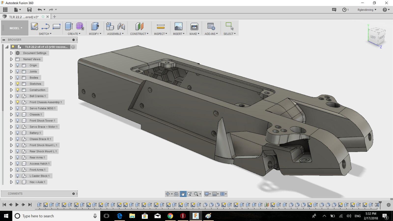
Anyways here are a few pics of the evolution of the CAD file.
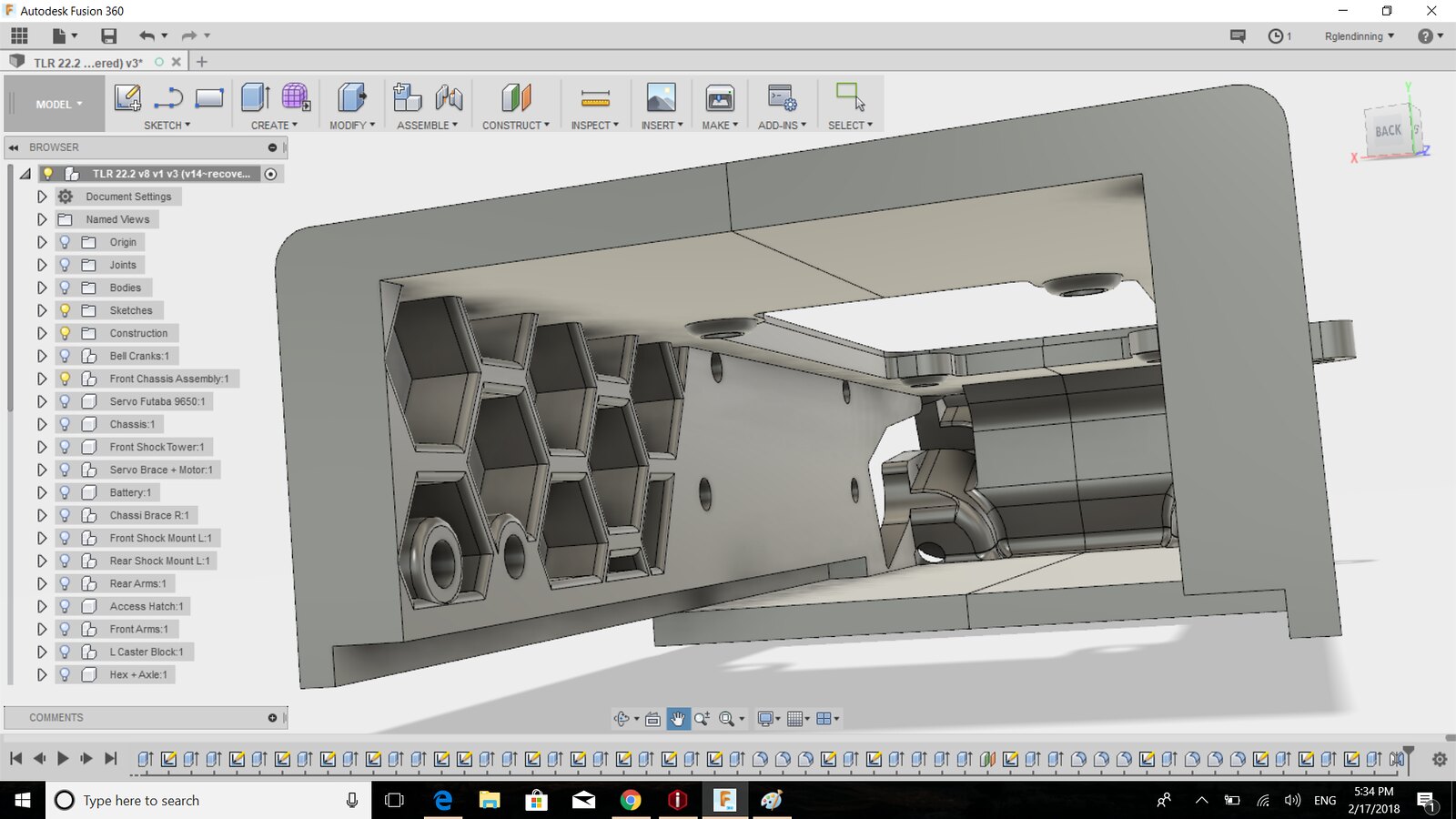
Inside the front monocoque.
 Buggy 46
 Buggy 45
 Buggy 44
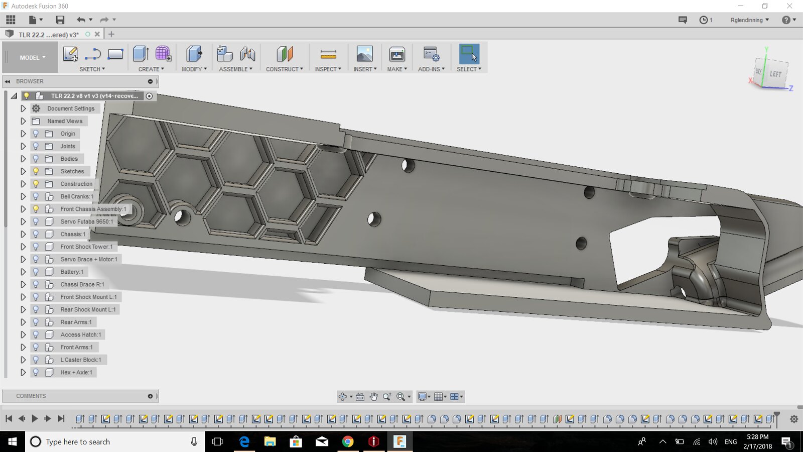
The monocoque split on half.
 Buggy 43
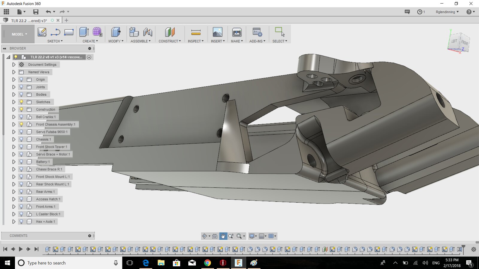
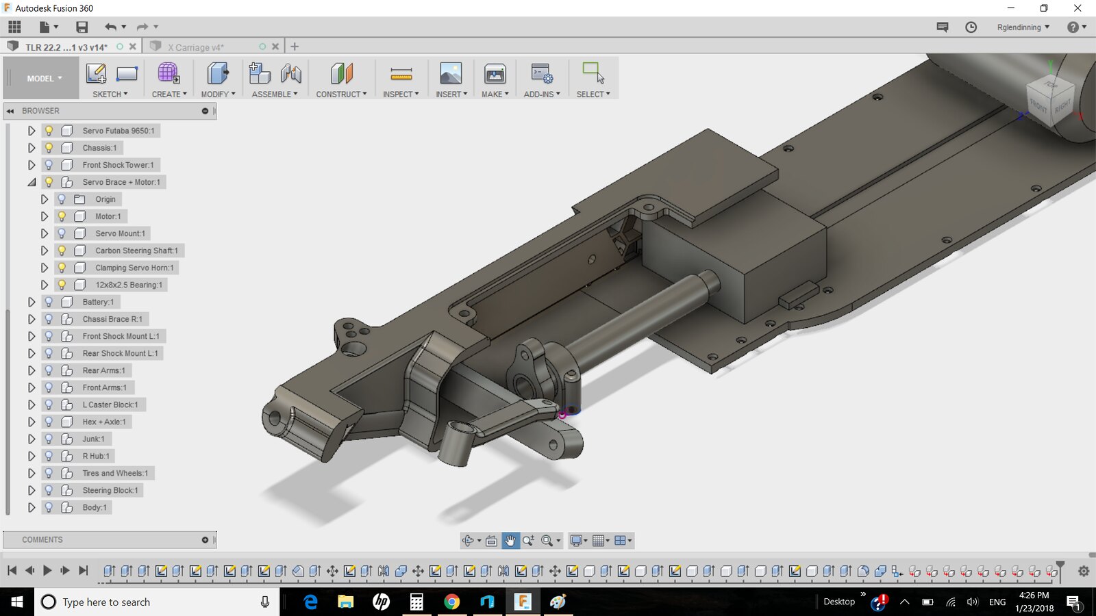
And finally a sneak peak of how the steering will work.
 Buggy 42
The printer is patched together at this point and id doing pretty good prints on the temporary parts. I am going to go a few test prints in PLA so I can see the parts, before doing the conversion to the new X carriage.
Anyways here are a few pics of the evolution of the CAD file.
Inside the front monocoque.
Buggy 46Buggy 45Buggy 44The monocoque split on half.
Buggy 43And finally a sneak peak of how the steering will work.
Buggy 42
03-29-2018, 11:07 PM
#105
Its been a while and I haven't posted anything because most of the stuff I have been doing (aside from work) has been on the printer. I have been trying to get the X carriage figured out with two nozzles.....
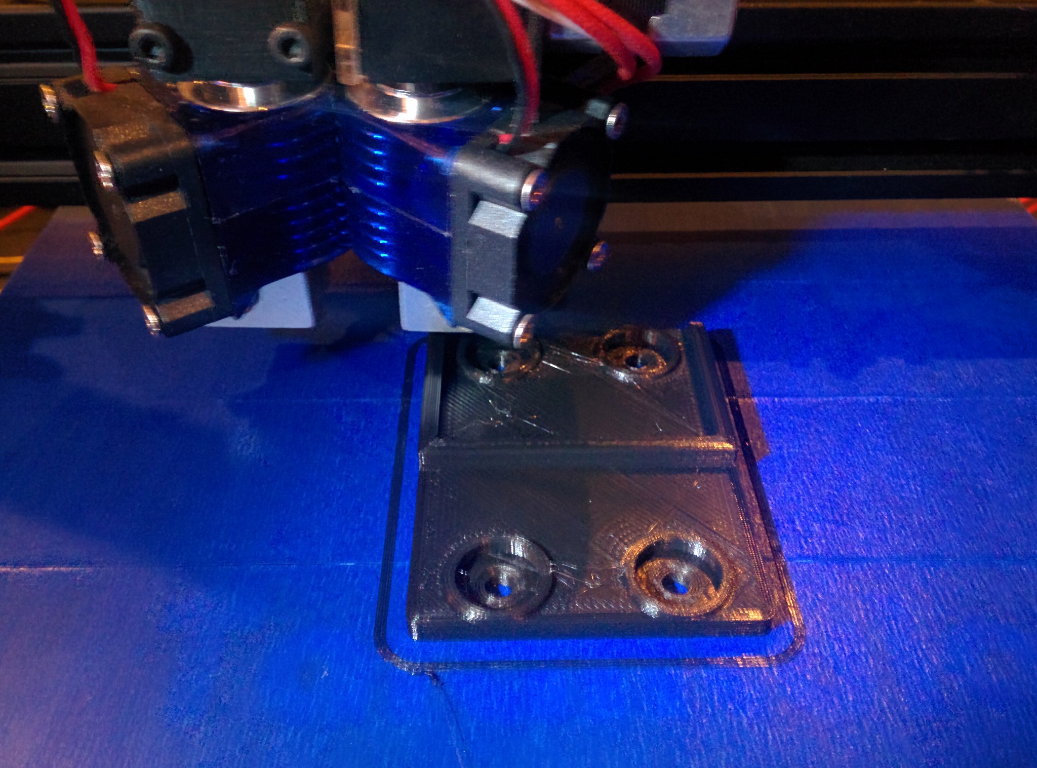
After a few tries I have temporarily given up on the two nozzle thing. For now!!!
I made a modular X carriage that I can later adapt a dual nozzle setup to.
 IMG_20180319_211759[1]
 IMG_20180319_211804[1]
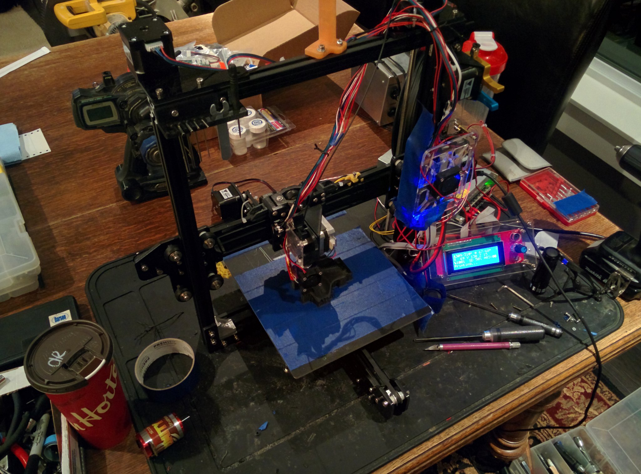
I used my last dual nozzle setup to print a better single nozzle setup. Here is where the printer is at at this point. It is a mess because I am still in the modifying and fabricating phase while prototyping a 2WD buggy! Makes sense right?
 IMG_20180329_212457[1]
This is the printer as I am writing this. How many people are fabricating an rc car that they designed with a 3d printer still in the development stage on a 100 year old oak table? And yes that is masking tape stopping the cooling fan from blowing on the print.
Ok.... So I have been on spring break for about a week and a half now and I have made a ton of progress on both the printer and the car. As I have been printing parts I have been noticing things wrong with my design (I am technologically illiterate), and problems that need to be solved with the printer, as well as fit and finish with the parts, so many of the parts are a multi step process.
 IMG_20180319_211913[1]
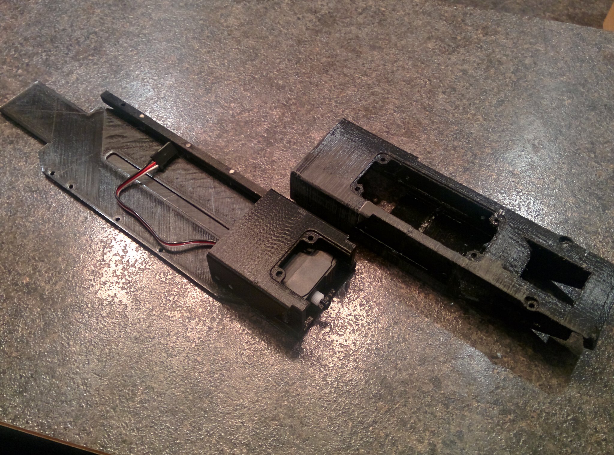
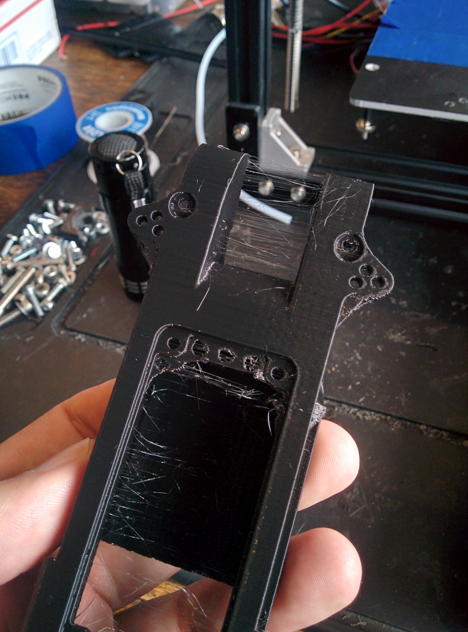
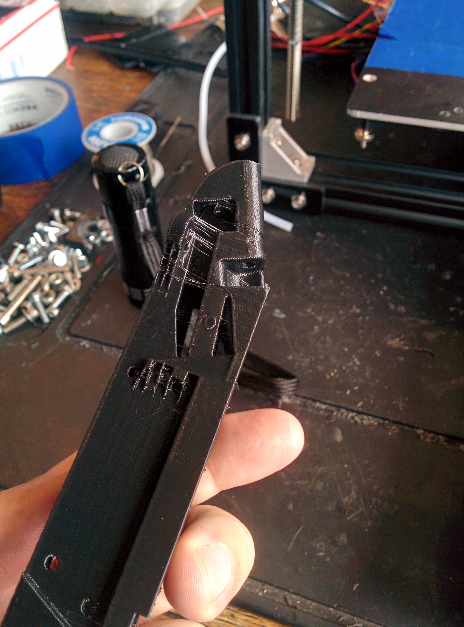
So just for the prototyping phase I printed a chassis, the real one will be a modified 22 chassis. A while ago I printed the front monocoque as a test. This lead to the redesign of the front monocoque. Then I started another test print and aborted after I noticed a bunch of things that I forgot (that's the short one on the left). You can see it attached to the mock-up chassis with the servo in it, which fit great!
 IMG_20180319_212020[1]
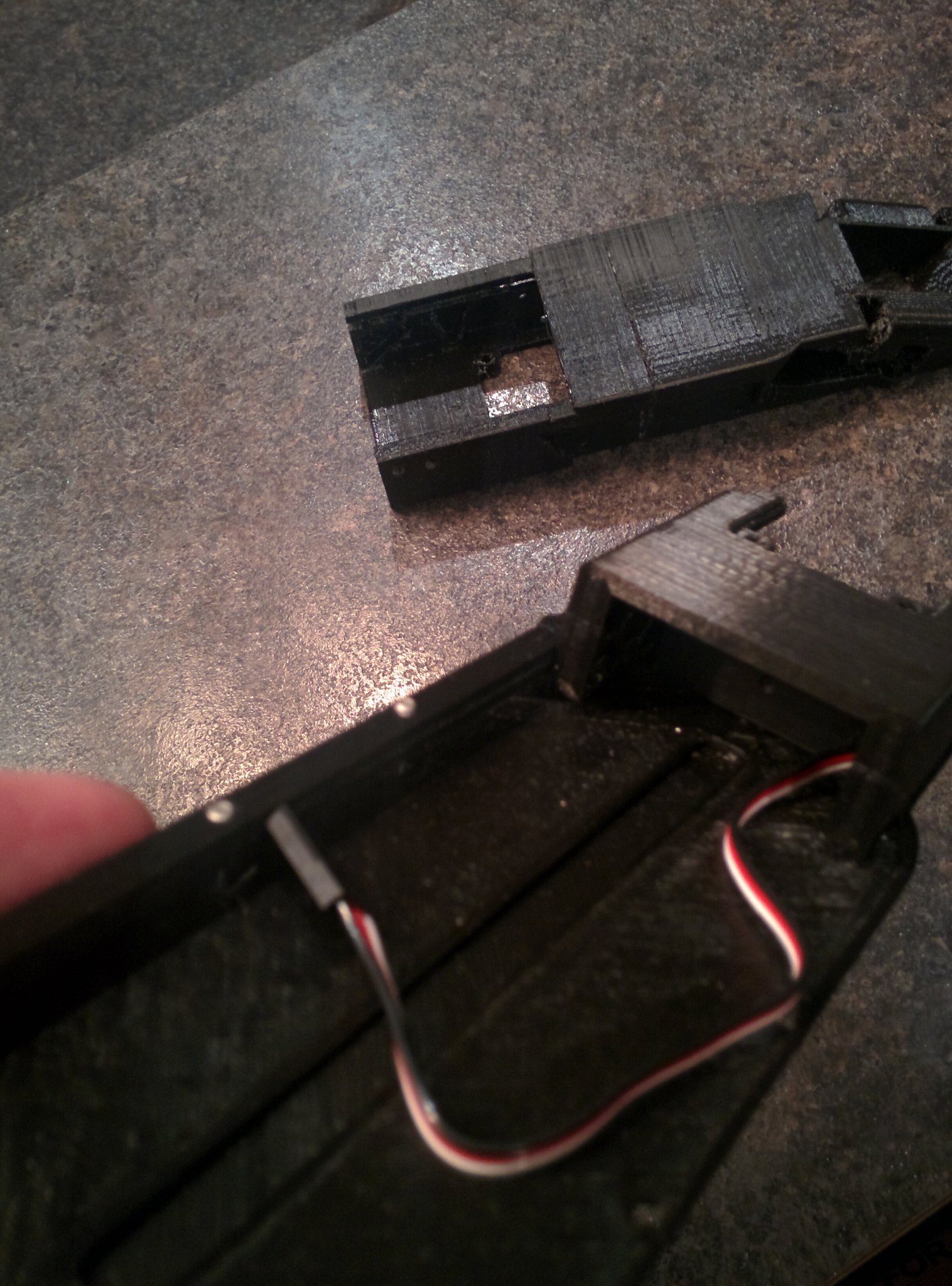
At that point I was pretty sure I had the monocoque design figured out so I did another test print. At this point the only way I can print this is with it standing vertically. It was at this point that I realized there is too much slop in the Y carriage to do this, but for the prototype this will be OK.
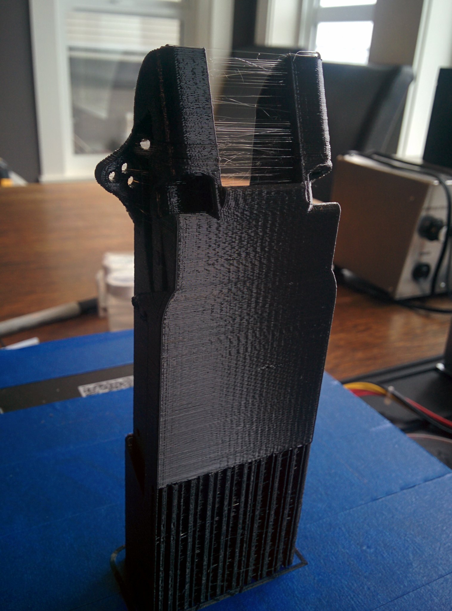 IMG_20180322_103218[1]
 IMG_20180322_103411[1]
 IMG_20180322_103416[1]
There is some stringing at this point with the PLA filament but I am not concerned about this.
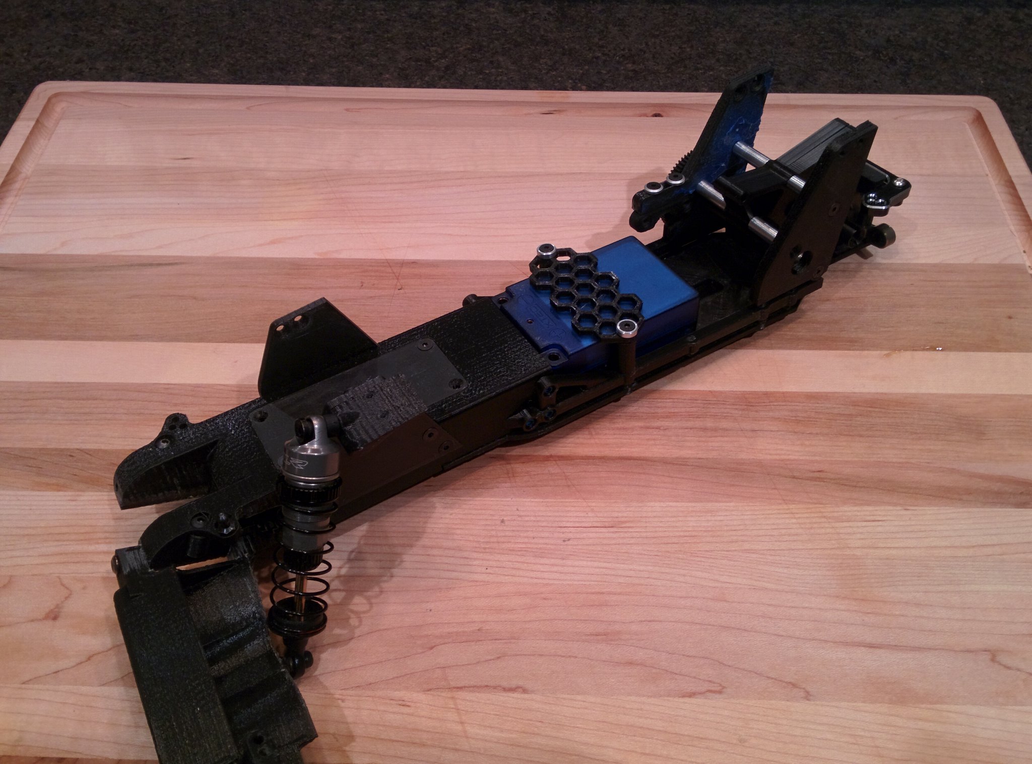
As of right now here is what it looks like. Super happy with everything at this point except for the caster blocks and steering knuckles. Hopefully Ill address this in the next couple of days.
 IMG_20180329_212214[1]
 IMG_20180329_212244[1]
 IMG_20180329_212305[1]
I redesigned the rear towers and finalized the design for the motor mount. These will be made in aluminium but prototyped in plastic. This side was one of my first semi successful Nylon/Carbon prints. This stuff is hard to get right! I have basically spent the last day and a half trying to get one of my carbon filament to print properly. Still no luck printing PETG/Carbon. Nylon/Carbon seems a bit easier.
 IMG_20180329_211946[1]
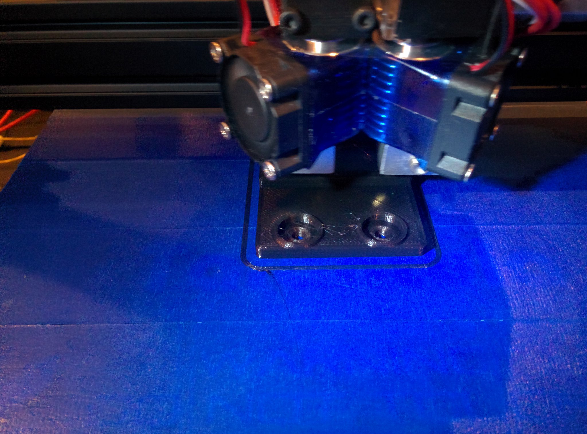
Here is a rear arm being printed right now in Nylon/Carbon. The finish is looking pretty good.
 IMG_20180329_212317[1]
I modified the chassis braces and incorporated a battery tie-down. I really like the way that it all turned out.
 IMG_20180329_212330[1]
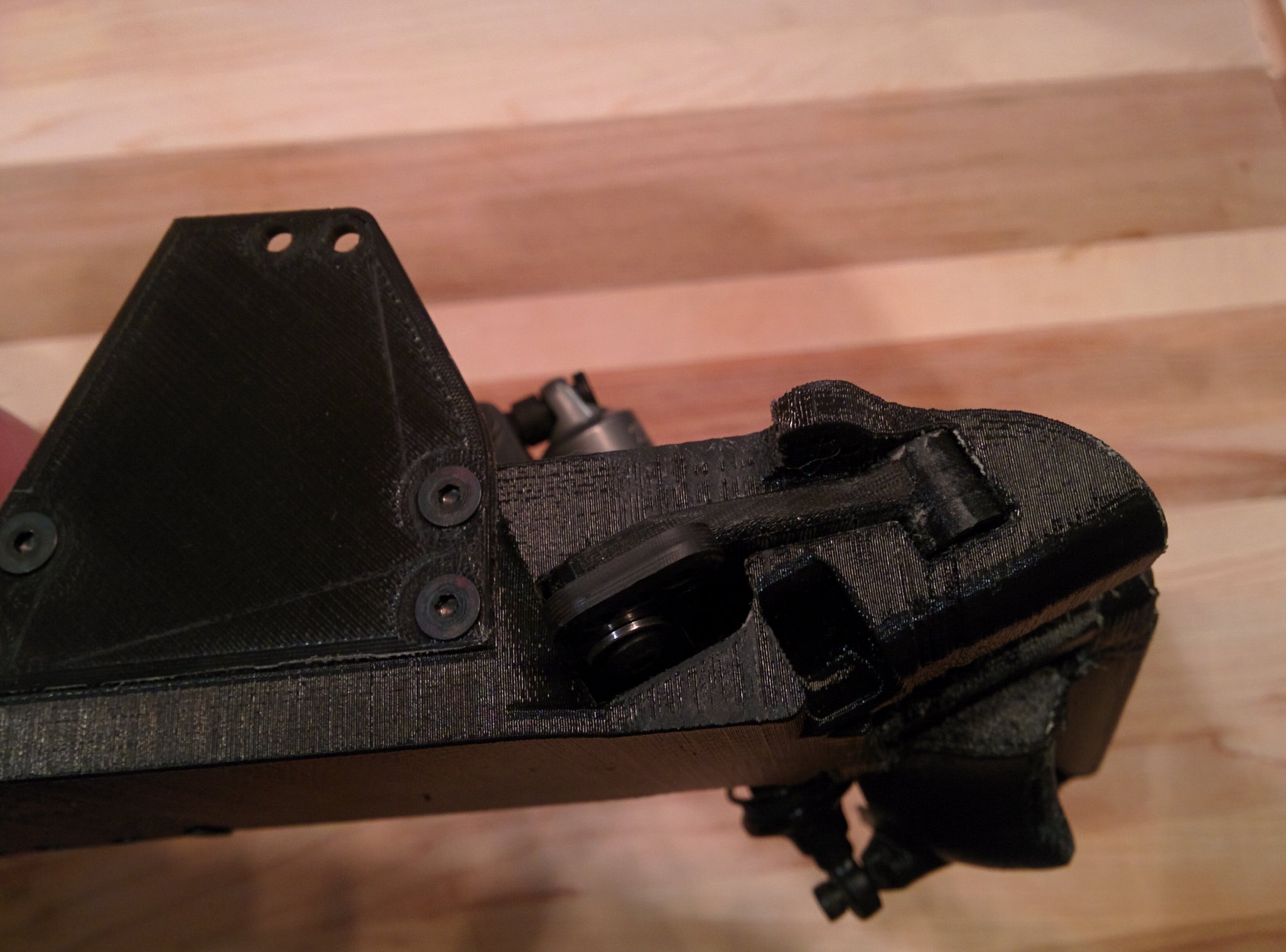
I changed the front shock mount a bit to get the geometry where I want it. This is also the mounting point for the front wing. Also the front shock towers will be made from sheets of carbon fiber. These are just prototypes.
 IMG_20180329_212349[1]
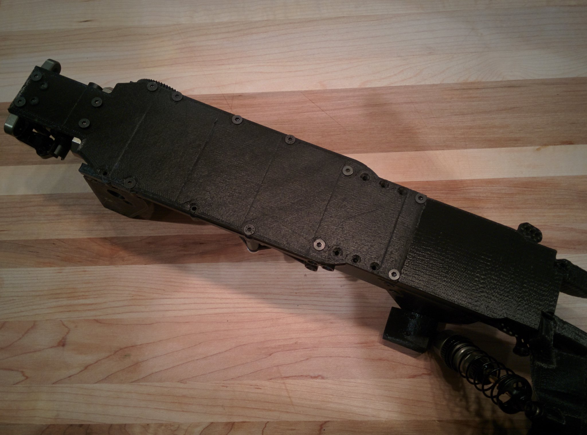
The bottom. Nothing really new here.
 IMG_20180329_212409[1]
Steering bell cranks. There might still be a bit of change here. I've got to play with this a bit to see if I like it. The other concern is geometry. I have to get everything mocked up to check it. Bump steer and clearance are my major concerns.
Hopefully Ill have more picks soon. It's Thursday and I don't work until Tuesday so I should be able to get lots done.
After a few tries I have temporarily given up on the two nozzle thing. For now!!!
I made a modular X carriage that I can later adapt a dual nozzle setup to.
IMG_20180319_211759[1]IMG_20180319_211804[1]I used my last dual nozzle setup to print a better single nozzle setup. Here is where the printer is at at this point. It is a mess because I am still in the modifying and fabricating phase while prototyping a 2WD buggy! Makes sense right?
IMG_20180329_212457[1]This is the printer as I am writing this. How many people are fabricating an rc car that they designed with a 3d printer still in the development stage on a 100 year old oak table? And yes that is masking tape stopping the cooling fan from blowing on the print.
Ok.... So I have been on spring break for about a week and a half now and I have made a ton of progress on both the printer and the car. As I have been printing parts I have been noticing things wrong with my design (I am technologically illiterate), and problems that need to be solved with the printer, as well as fit and finish with the parts, so many of the parts are a multi step process.
IMG_20180319_211913[1]So just for the prototyping phase I printed a chassis, the real one will be a modified 22 chassis. A while ago I printed the front monocoque as a test. This lead to the redesign of the front monocoque. Then I started another test print and aborted after I noticed a bunch of things that I forgot (that's the short one on the left). You can see it attached to the mock-up chassis with the servo in it, which fit great!
IMG_20180319_212020[1]At that point I was pretty sure I had the monocoque design figured out so I did another test print. At this point the only way I can print this is with it standing vertically. It was at this point that I realized there is too much slop in the Y carriage to do this, but for the prototype this will be OK.
IMG_20180322_103218[1]IMG_20180322_103411[1]IMG_20180322_103416[1]There is some stringing at this point with the PLA filament but I am not concerned about this.
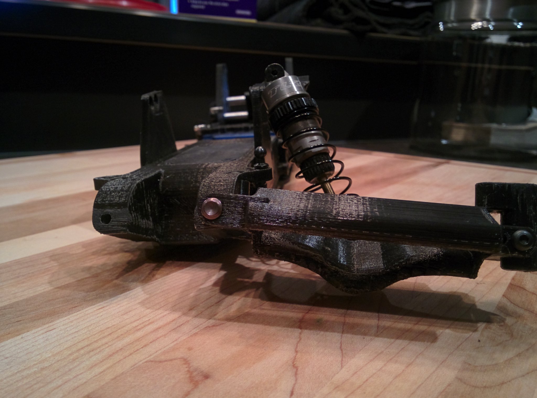
As of right now here is what it looks like. Super happy with everything at this point except for the caster blocks and steering knuckles. Hopefully Ill address this in the next couple of days.
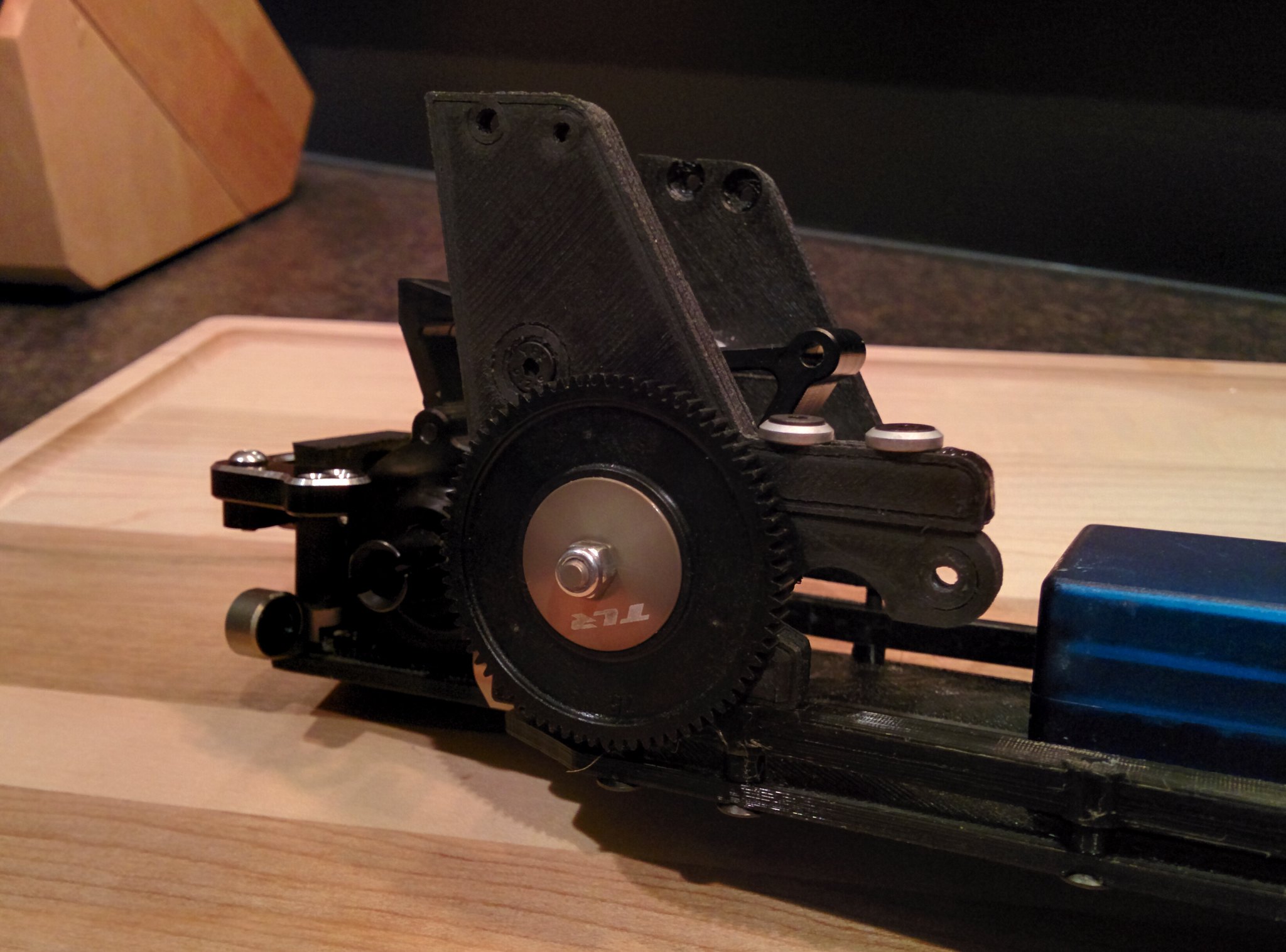
IMG_20180329_212214[1]IMG_20180329_212244[1]IMG_20180329_212305[1]I redesigned the rear towers and finalized the design for the motor mount. These will be made in aluminium but prototyped in plastic. This side was one of my first semi successful Nylon/Carbon prints. This stuff is hard to get right! I have basically spent the last day and a half trying to get one of my carbon filament to print properly. Still no luck printing PETG/Carbon. Nylon/Carbon seems a bit easier.
IMG_20180329_211946[1]Here is a rear arm being printed right now in Nylon/Carbon. The finish is looking pretty good.
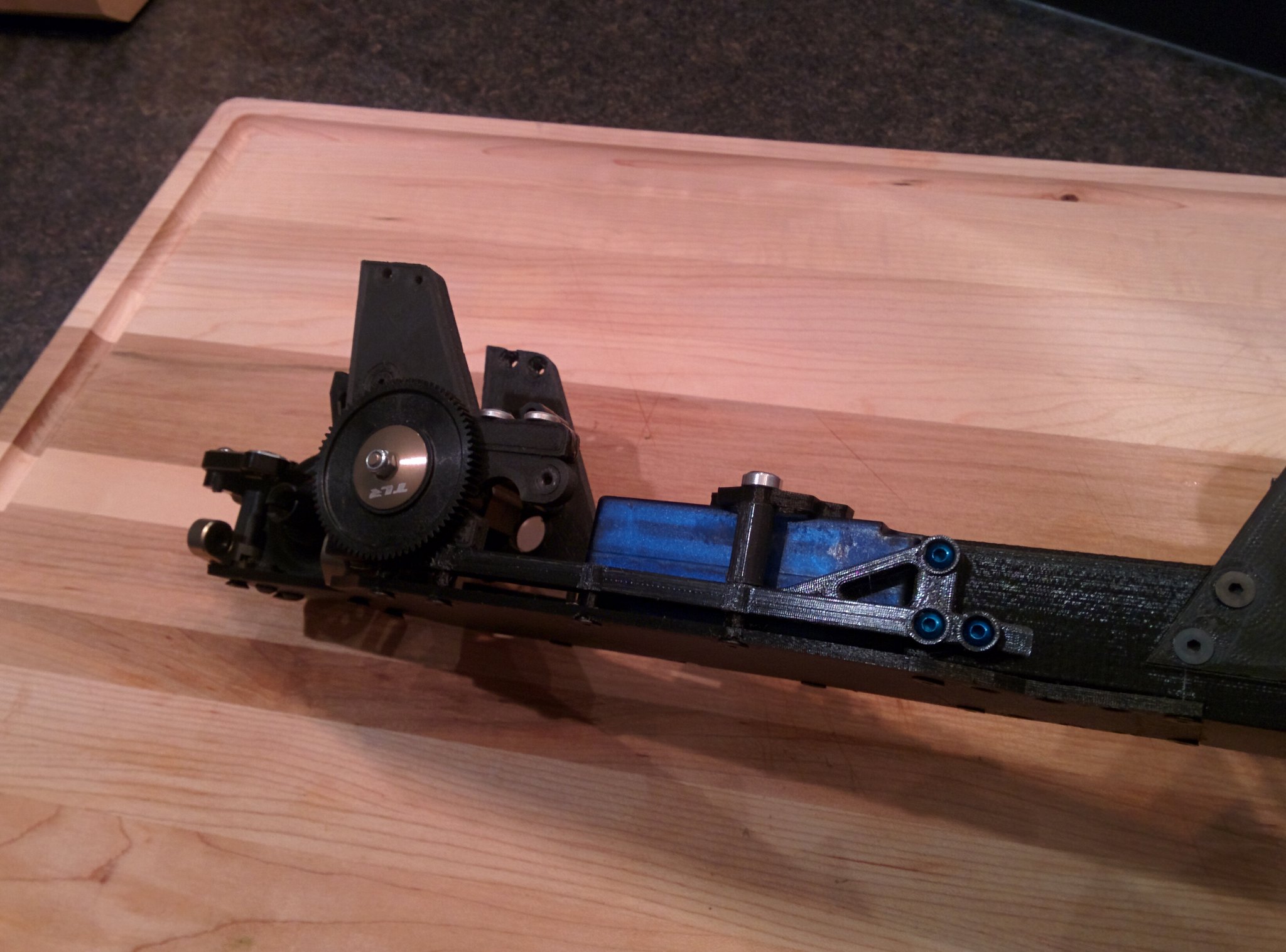
IMG_20180329_212317[1]I modified the chassis braces and incorporated a battery tie-down. I really like the way that it all turned out.
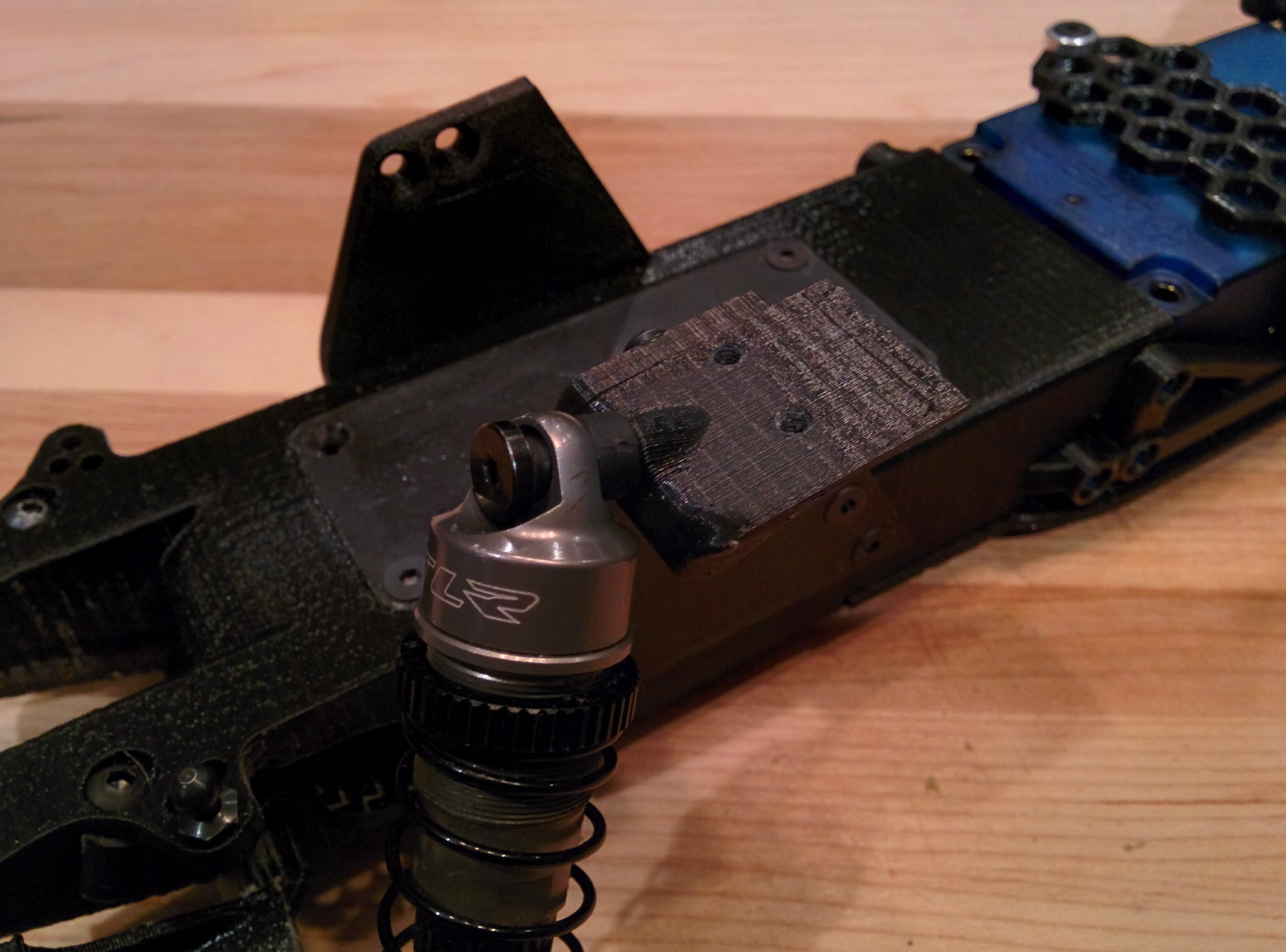
IMG_20180329_212330[1]I changed the front shock mount a bit to get the geometry where I want it. This is also the mounting point for the front wing. Also the front shock towers will be made from sheets of carbon fiber. These are just prototypes.
IMG_20180329_212349[1]The bottom. Nothing really new here.
IMG_20180329_212409[1]Steering bell cranks. There might still be a bit of change here. I've got to play with this a bit to see if I like it. The other concern is geometry. I have to get everything mocked up to check it. Bump steer and clearance are my major concerns.
Hopefully Ill have more picks soon. It's Thursday and I don't work until Tuesday so I should be able to get lots done.