


 2Likes
3 Racing Sakura D3 CS Drift
 05-12-2013, 09:27 PM
#1801
Tech Adept
Hey guys im pretty keen on doing some drifting just wondering would i have buy a drift chassis like the d3 or can i still use the s zero and if i can what changes do i have to do?
Thanks
Thanks
 05-13-2013, 09:01 AM
#1802
http://forum.driftmission.com/Thread...s#.UZEOAaKG0rU
05-13-2013, 12:37 PM
#1803
I have my D3CS and had a go drifting it last night. The surface was concrete, the car setup was box stock, and all it wanted to do was donut, very little control. Any setup ideas?
No upgrades (yet)
Alturn cheapy servo
Nosram cheapy brushed ESC
Etronix cheapy 19t motor
Vapextech cheapy 3300mah LiPo
KO Vantage 3 radio with Spektrum module and receiver
Here it is with my Reely Audi RS6 S-Line body, the tyres are the kit sparking ones and wheels are alloy Rota Grid replicas with 7mm of offset, and I used 3mm of shims to make it 200mm; though I won't run it like that as there is literally hardly any thread on the wheelnuts to hold them on . Out of the box though, it has waaaay too much front end grip so it needs some setup work to stop it just doing donuts.


No upgrades (yet)
Alturn cheapy servo
Nosram cheapy brushed ESC
Etronix cheapy 19t motor
Vapextech cheapy 3300mah LiPo
KO Vantage 3 radio with Spektrum module and receiver
Here it is with my Reely Audi RS6 S-Line body, the tyres are the kit sparking ones and wheels are alloy Rota Grid replicas with 7mm of offset, and I used 3mm of shims to make it 200mm; though I won't run it like that as there is literally hardly any thread on the wheelnuts to hold them on
. Out of the box though, it has waaaay too much front end grip so it needs some setup work to stop it just doing donuts.Where did you get you're body from
05-13-2013, 12:50 PM
#1804
A quick search for Reely RC car bodies yeilded this result:
http://www.idealo.co.uk/compare/1630...rs6-black.html
http://www.idealo.co.uk/compare/1630...rs6-black.html
05-14-2013, 12:11 PM
#1805
A quick search for Reely RC car bodies yeilded this result:
http://www.idealo.co.uk/compare/1630...rs6-black.html
http://www.idealo.co.uk/compare/1630...rs6-black.html
05-14-2013, 02:48 PM
#1806

You don't NEED to get a dedicated drift chassis, but once you drive one you'll probably want one. Check out Eunique's build of his Zero S on Drift Mission:
http://forum.driftmission.com/Thread...s#.UZEOAaKG0rU
http://forum.driftmission.com/Thread...s#.UZEOAaKG0rU
 that place is awesome
05-14-2013, 07:13 PM
that place is awesome
05-14-2013, 07:13 PM
#1807
D3 kits and some hopup parts are back in stock.
http://www.tqrcracing.com/shop/produ...id=56&s_sort=4
FTI, thanks.
http://www.tqrcracing.com/shop/produ...id=56&s_sort=4
FTI, thanks.
05-15-2013, 07:51 AM
#1808
Anyone know which aluminum control arms will fit the d3 ? I'm after front & back arms.
Thanks in advance.
Thanks in advance.
05-15-2013, 08:08 AM
#1809
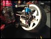
After having the parts for the KPI mod for several weeks I finally got to work on the conversion last night. Thanks to pickled, I had everything I needed. Thanks, man!!
First of all, here's some pics... You'll notice that most of my endlinks and ball studs are now Team Associated parts. Reduced a lot of slop and much more serviceable.


I should also point out that I have not done any kind of alignment yet, haven't set right height, track width, etc. I don't even know what my camber is yet, but I tried to replicate what I had with the stock setup, only with a very slightly narrower track width (maybe 1-2mm overall). My reason behind that is so I can run less negative camber to fit my 7mm offset wheels. The Ackerman looks half way decent, I think.
It's raining outside so I can't go test it. And driving it around the kitchen or dining room isn't exactly what I'd call a "thorough" test. But here's some random thoughts I have so far.
I tried to be as careful as I could as I made these mods. I wanted the suspension geometry left:right to be as identical as possible and with the drilling/cutting required, it's very easy to screw this up. Despite my efforts, I'm pretty sure it's not nearly as symmetric as I'd like. Maybe it won't be an issue? It's times like these I really wish I had a machine shop.
There's quite a bit of play at the axle/steering arm area. I'm only running one bearing in each steering arm 'cause that's all there's room for. pickled, did you only run one bearing per side? Did you notice any excessive slop? It's possible I'm just being too picky, but I have no other gauge besides the stock setup and my Associated racecars.
The upper arms introduce a bit of fore/aft play. If I tighten the screw that attaches it to the shock tower it gets better....but at the expense of more friction that prevents the suspension from moving very easily. I added a drop of oil in there and it's better. We'll see how it does after it breaks in some.
I also noticed that the steering arms will contact the axle shaft at full lock! I would trim them, but the car gets some chatter before then so I adjusted my endpoints. Now there's no chatter, but I don't get quite as much steering throw. It still has plenty, though.
I'm hoping to tune down the CS from 214% to 156% this week. Maybe between that and the increased steering throw I can finally make this thing driveable!
First of all, here's some pics... You'll notice that most of my endlinks and ball studs are now Team Associated parts. Reduced a lot of slop and much more serviceable.
I should also point out that I have not done any kind of alignment yet, haven't set right height, track width, etc. I don't even know what my camber is yet, but I tried to replicate what I had with the stock setup, only with a very slightly narrower track width (maybe 1-2mm overall). My reason behind that is so I can run less negative camber to fit my 7mm offset wheels. The Ackerman looks half way decent, I think.
It's raining outside so I can't go test it. And driving it around the kitchen or dining room isn't exactly what I'd call a "thorough" test.
But here's some random thoughts I have so far.I tried to be as careful as I could as I made these mods. I wanted the suspension geometry left:right to be as identical as possible and with the drilling/cutting required, it's very easy to screw this up. Despite my efforts, I'm pretty sure it's not nearly as symmetric as I'd like. Maybe it won't be an issue? It's times like these I really wish I had a machine shop.
There's quite a bit of play at the axle/steering arm area. I'm only running one bearing in each steering arm 'cause that's all there's room for. pickled, did you only run one bearing per side? Did you notice any excessive slop? It's possible I'm just being too picky, but I have no other gauge besides the stock setup and my Associated racecars.
The upper arms introduce a bit of fore/aft play. If I tighten the screw that attaches it to the shock tower it gets better....but at the expense of more friction that prevents the suspension from moving very easily. I added a drop of oil in there and it's better. We'll see how it does after it breaks in some.
I also noticed that the steering arms will contact the axle shaft at full lock! I would trim them, but the car gets some chatter before then so I adjusted my endpoints. Now there's no chatter, but I don't get quite as much steering throw. It still has plenty, though.
I'm hoping to tune down the CS from 214% to 156% this week. Maybe between that and the increased steering throw I can finally make this thing driveable!
05-15-2013, 03:45 PM
#1810
Tech Initiate
Sorry for the long first post. I've been lurking and learning for a while and figured that it was time to contribute.
With the MST knuckles and MST axle shafts, the CVD cup itself sets inside of a 10 X 15 X 4 bearing (Same size as the diff bearings). The knuckles should have come with a 5 X 11 X 4 bearing for the outside, since this is a less common size. With the larger bearing and its position being closer to the CVD pivot, this setup has noticeably less slop than stock (once properly shimmed). I have the aluminum short arm MST knuckles, but I'm assuming the long arm plastic ones are the same. Note that the offset adapter mounted on the top of my MST knuckle is to move the steering axis inboard of the CVD pivot to eek out a few more degrees of steering. The shafts now move slightly in the direction of the turn, instead of slightly opposed. I'm using the inner hole on the bottom of the knuckle, so the KPI is roughly the same as yours. I've used the outer hole on the bottom for more KPI, but toned it back down as described below.
The plastic shock tower has a ton of fore/aft flex at the upper link holes, despite the proximity to the bulkhead screws. Not sure if you have the screw going from one side of the Yokomo arm, threaded through the shock tower, then sticking through the hole in the other side of the Yok arm, or a short screw in both sides? Either way, the Yok arm is pivoting on threads. Meaning, as soon as it 'Breaks in," it will wear out. Since the Yok arm is designed to pivot on a 3mm hinge pin, you might have better results using an M3 screw that isn't fully threaded. Find a screw with the right shoulder length and cut any excess threads off. Then, washers at every interface and a locknut on the far side. You may need to accurately drill out the 3mm hole in the shock tower, as the snugness in the thru-joint can cause uneven pressure making it difficult to get the right tightness on the locknut. The D3 carbon fiber front shock tower will help a lot with stiffness and is a worthwhile upgrade for 'serviceability' as well. The camber link holes are also perfectly drilled for a 3mm pin/shaft/bolt of your choosing, which makes it so much easier to maintain symmetry with this mod.
I ended up using a set of IFS pivots for the top links which are virtually slop free (once shimmed). I did have to plan ahead regarding the desired caster range, since the front face of the shock tower is roughly where the upper pivot is 'designed' to be. The pivot post can be shimmed to alter caster in one direction only, so you need to drill the lower link hole fore/aft to suit your needs. I mounted mine to the rear face of the tower, so I can shim for more positive caster. I also wanted to keep the front clear for more suspension hardware. In my case, the left and right pivots are coupled by a roll spring/damper, which carries about 80% of the front end weight and keeps the chassis nearly flat as the wheels go lock to lock. The dual rate vertical springs are extremely soft, but help return the chassis to neutral and while also curtailing excessive body roll.
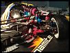
Pickled's approach is hand's down the easiest and cleanest way to achieve KPI on the D3, and many, including myself have benefited from the legwork he and others did in the early days of this chassis. Unfortunately, his work has 'inspired' me down the path to addiction, and KPI was the gateway drug. Once I had a little KPI, I wanted more, then more caster, then articulating front and rear suspension to accommodate the substantially increased rise/fall of the outside/inside wheel contact patches, etc... I'm now running a full posican setup with 20* caster and ~12* KPI at 2.34 CS and it will do high speed switchbacks from gutter to gutter on a rough residential asphalt street with excellent control. I can toss it quite aggressively and it maintains composure without spinning out. This is significant because I'm a noob with just a little over 2 months in this sport after a 20 year hiatus from RC cars. I've taken it as high as 25* caster and ~18* KPI, which allowed even higher drift speeds, but it understeered too much at low speed, sacrificing fine control around the cones. It was pretty cool doing perfect sweepers around a culdesac sidewalk though.
Posican is definitely not everyone's cup of tea, but it's worth noting that KPI is a definitive step in that direction. KPI will add positive camber to both wheels in both directions. Caster adds positive camber to the inside wheel, and negative to the outside wheel. So with caster of 10*, KPI at 10* and static camber at 0*, the inside wheel will lean outward or lay over (Roughly 16* @ 55* steering angle), whereas the outside wheel will be nearly upright. Of course, the chassis will have to roll as the inside wheel pushes down, which will shift the resultant numbers, but you get the idea. Notice in the picture above that my inside wheel is at about +28* and the outside is around -7*. By differing the ratio of caster to KPI, you can semi-independantly tune how the wheels behave when they are leading from when they are trailing, and thus their resulting lateral and longitudinal traction vectors. Coupled with radiused tires, the contact patch, which does in fact still change, gradually rolls across the width of the tire as it steers lock to lock, which greatly reduces the twitchyness caused by abrupt front-end traction changes. It may look a bit janky, but when you see it all work, it makes so much sense. Well, that's my understanding through lots of tinkering anyway
05-16-2013, 02:07 AM
#1811
Caseymacgyver thanks for your glowing revue lol!
Tommy R you need to run the axle in a 10x15x4 bearing same as the bulkhead bearings I never ran mine with only one bearing in the knuckles

I recommend bracing the upper arms to the chassis like combat drifter has on his D3 you can find images on drift mission forum
Tommy R you need to run the axle in a 10x15x4 bearing same as the bulkhead bearings I never ran mine with only one bearing in the knuckles
I recommend bracing the upper arms to the chassis like combat drifter has on his D3 you can find images on drift mission forum
05-16-2013, 03:54 AM
#1812
Tech Initiate
this is the upper arm mod
I think it's a must.. it reduces the vibrations a lot

BTW if you turn the turnbuckle so it pulls the upperarm back a little, you gain more caster and enhance the kpi effect
I think it's a must.. it reduces the vibrations a lot
BTW if you turn the turnbuckle so it pulls the upperarm back a little, you gain more caster and enhance the kpi effect
05-16-2013, 06:23 AM
#1813
Tech Regular
iTrader: (3)
You don't NEED to get a dedicated drift chassis, but once you drive one you'll probably want one. Check out Eunique's build of his Zero S on Drift Mission:
http://forum.driftmission.com/Thread...s#.UZEOAaKG0rU
http://forum.driftmission.com/Thread...s#.UZEOAaKG0rU
Sakuraszero..let me know if you need any help with your project.
05-16-2013, 06:27 AM
#1814
Caseymacgyver, thanks for all the info.! I'm still a bit unclear, however, regarding the upper arm pivots. It looks like they're on bearings and allowed to rotate, which necessitated the upper shock? Am I understanding that correctly? And you did this to address the jacking effect?
And you and pickled were right about the extra hub bearing! None of the components I bought came with one, but fortunately, it's the same size bearing that's used in Axial rock crawlers (my main RC interest) so I put some in yesterday and the slop is MUCH better now. So thanks!
My upper "Y" link that attaches to the shock tower is clearance drilled on one end. The shock tower is also clearanced. And then the screws threads into the other end of the "Y". If I keep it loose enough to get free movement, it introduces too much play. If I snug it up to eliminate the play, it's too tight and doesn't move freely. I think I'll look into what Exita did.
Exita, how did you attach the triangulated link to the camber link?