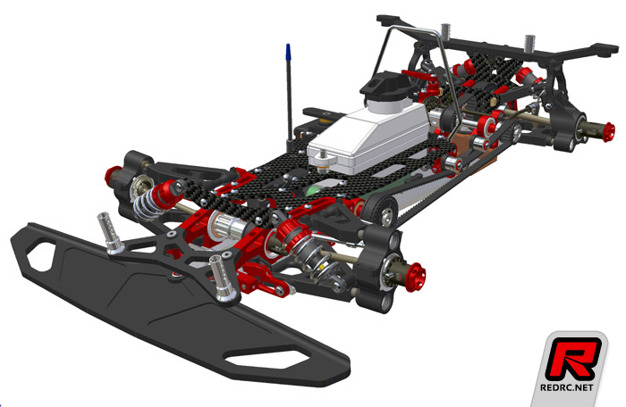
More info on the new 1/8 scale car of Capricorn was released today.
Some of the features:
-Fully floating radiotray
-Self adjusting side belt tensioner
-Very open design
-Easy maintenance
-Lightweight design
-High quality shock absorbers
More details at the Nurenburg Toyfair which will take place at the start of february.
Kits start shipping at the end of february.
Picture source:
http://www.redrc.net
Build report:
Finally had the time to do the write up for the build report of the C801.
So here it goes:
The box:
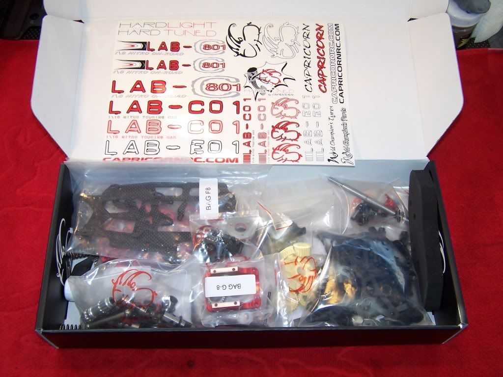
Inside the box:
 Step 1, Shockabsorbers.
This part I copied from my LAB-C01 report, so the shocks aren't the actual C801 shocks. The rear C801 shocks are longer then the C01 shocks.
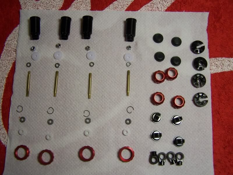
The quality of the shocks is amazing, standard they come with TiNi coated shafts and a mono O-ring design. The pistons and shaft guide are machined nylon which makes for the smoothest shock I ever build.
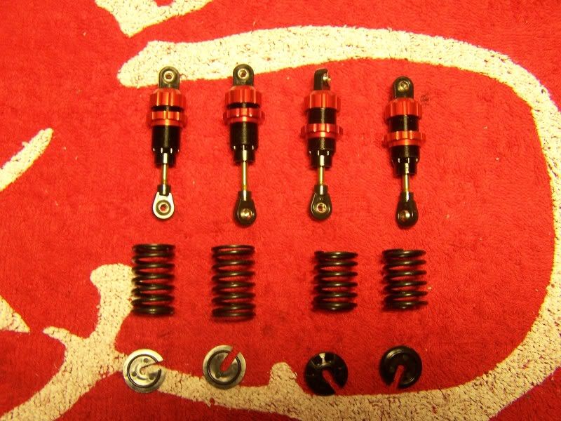
All shocks were perfectly matched in bound and rebound on the first try.
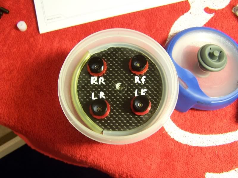
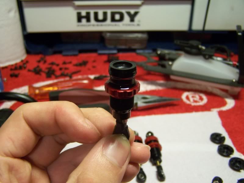
Bleeding the shocks with a vacuum pump, this makes for a perfect air-free shock.
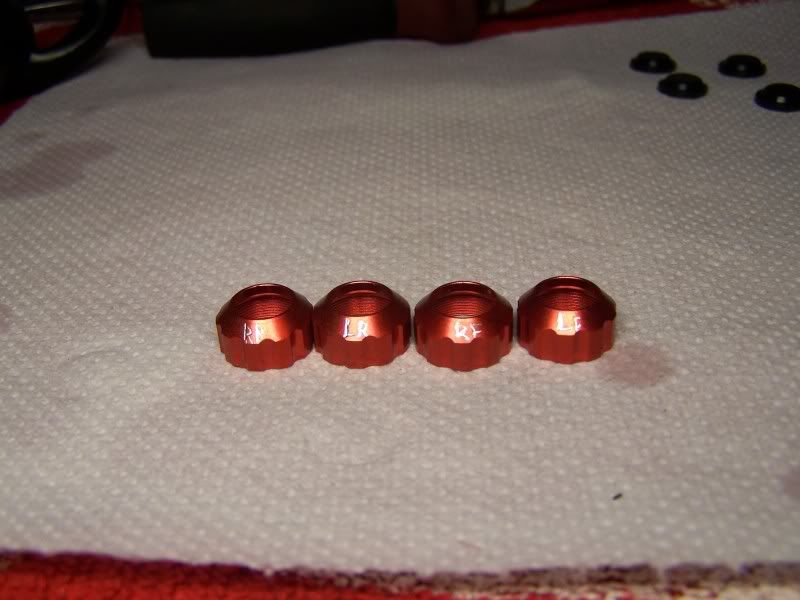
Meanwhile I engraved the shockcaps, this makes it easy to have the same shock on the same corner of the car every time.
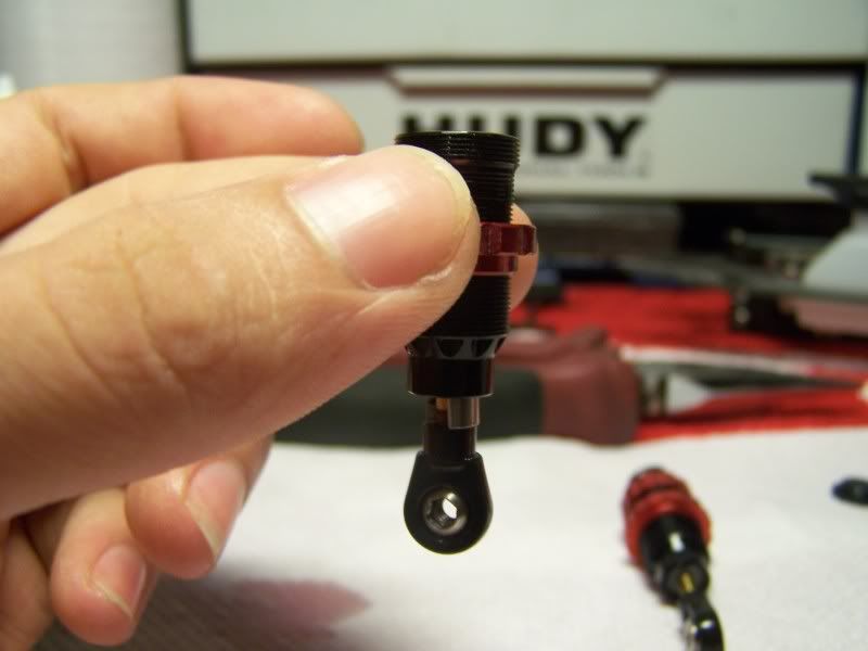
I used the following method while building the shocks:
1. Put a 4mm spacer between the damperhousing and the balljoint, this sets the amount of rebound. A small spacer will mean less rebound, a big spacer more rebound.
2. While pushing the shockshaft into the housing( with the spacer in place) place the membrane on top of the shockhousing. All excess oil will come out of the shock.
3. Screw the cap on top of the housing.
4. Check if both front and both rear dampers are equal, this is very important in terms of car balance.
I've build the dampers with 600cst oil and used 2 holed pistons all around.
 Step 2, Rear Axle
Parts for the rear axle:
As you can see the rear axle is fully lightened as standard and a kevlar reinforced pulley is used. The bearings are seated in eccenters machined out of delrin.
Assembled rear axle:
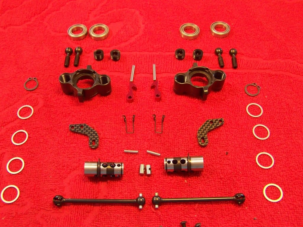
 Step 3, Front oneway axle
Parts for the oneway axle:
Also the front axle comes fully lightened as standard, both the oneway unit as the outdrives are machined to save as much weight as possible.
Bearings are seated in delrin bushings and the front pulley is also a kevlar reinforced one.
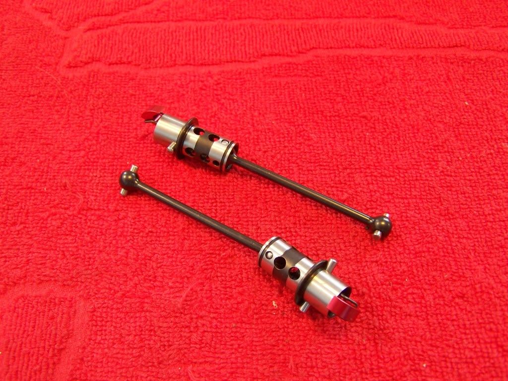
Hollow outdrives:
Assembled oneway axle:
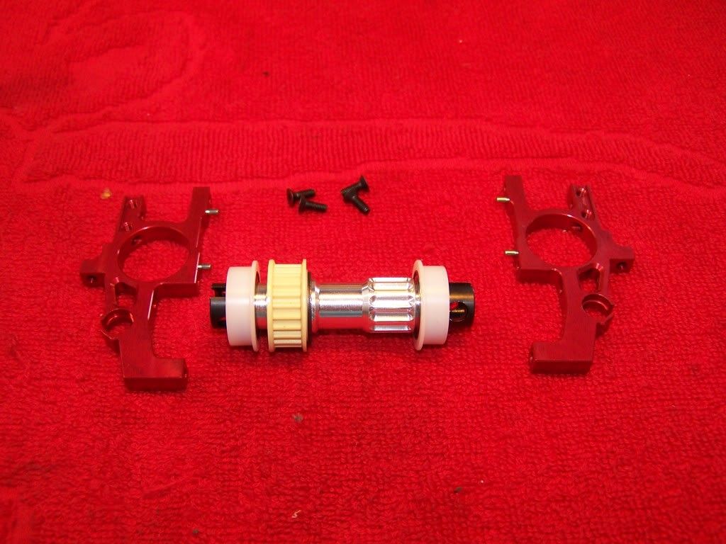
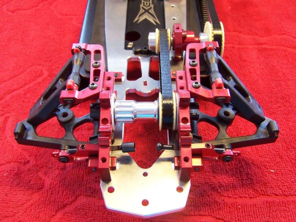
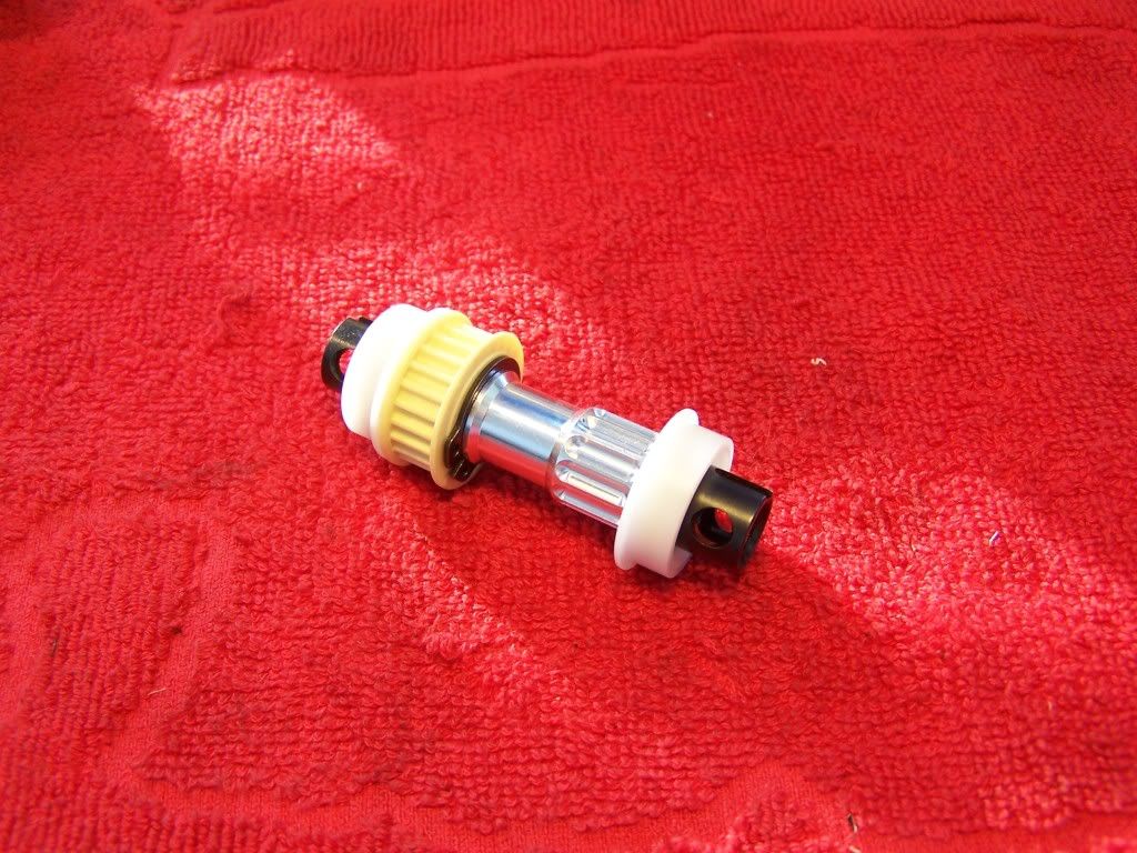 Step 4, Middle shaft holder
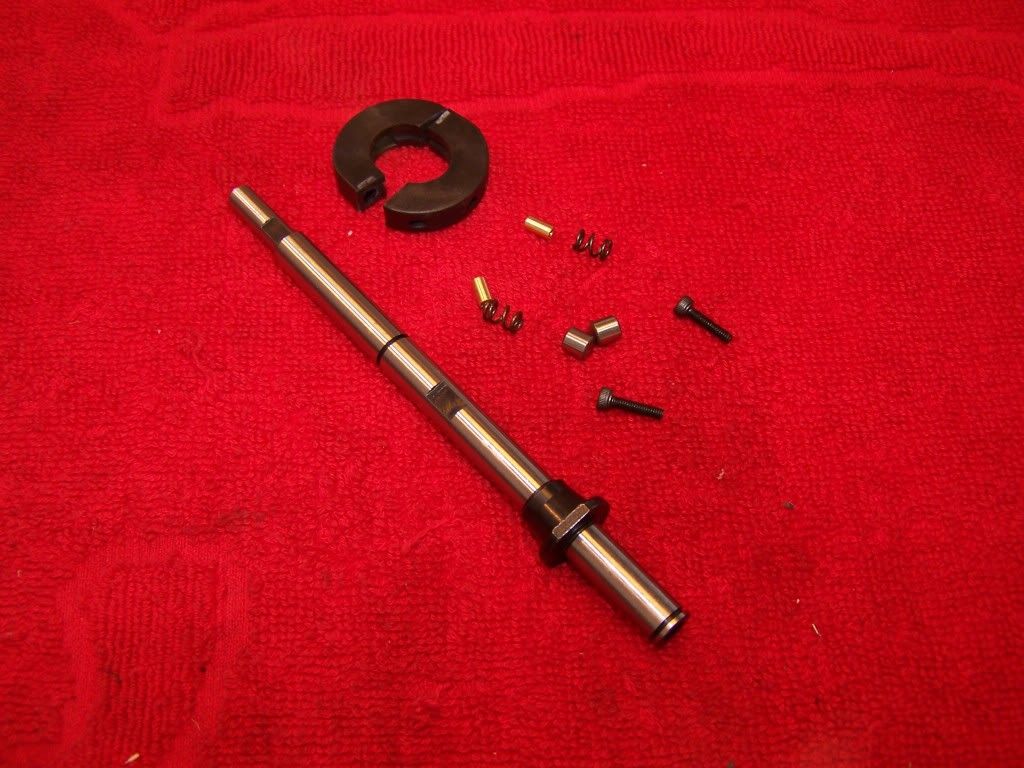
Parts for the middle shaft holder:
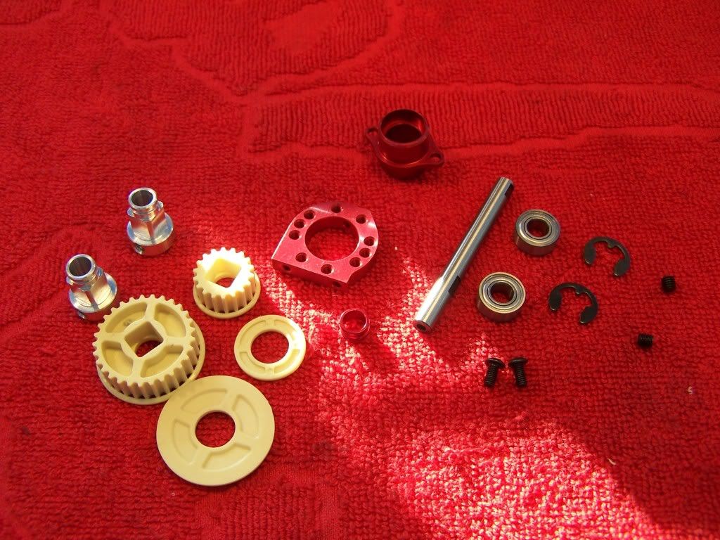
The axle is hollow to save weight and the pulleys are the kevlar reinforced ones.
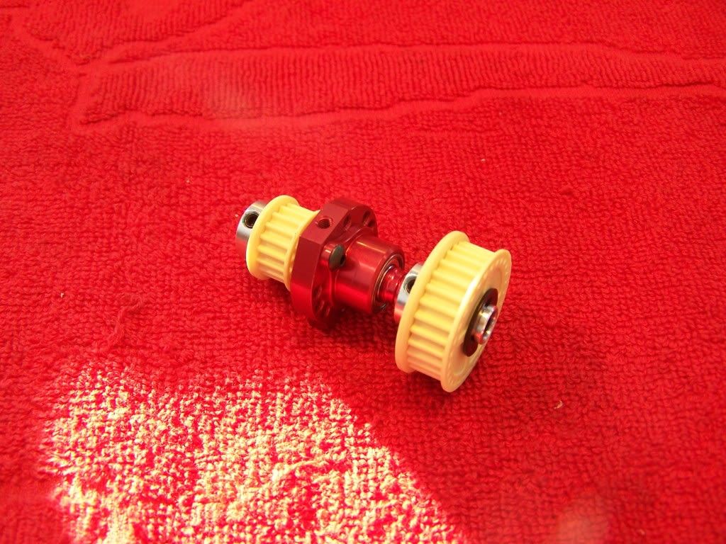
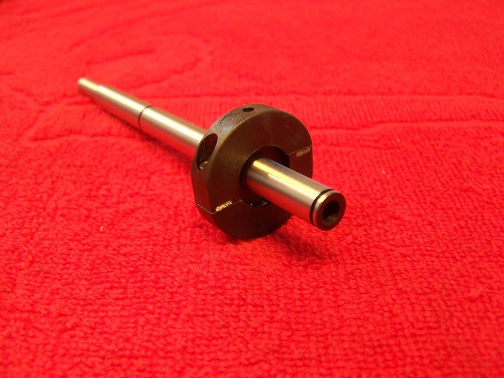
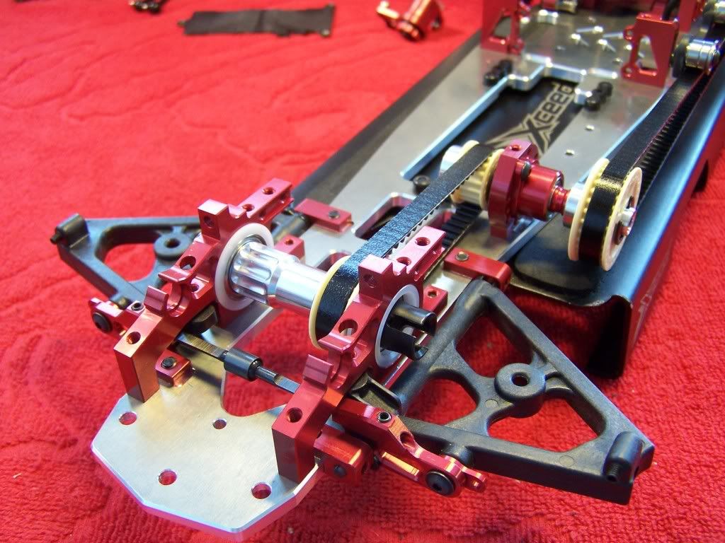
The middle axle holder is eccentric which gives you the ability to change the front belt tension very easily without any disassembly:
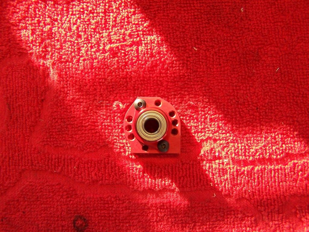
Complete assembly:
 Step 5, Gear box
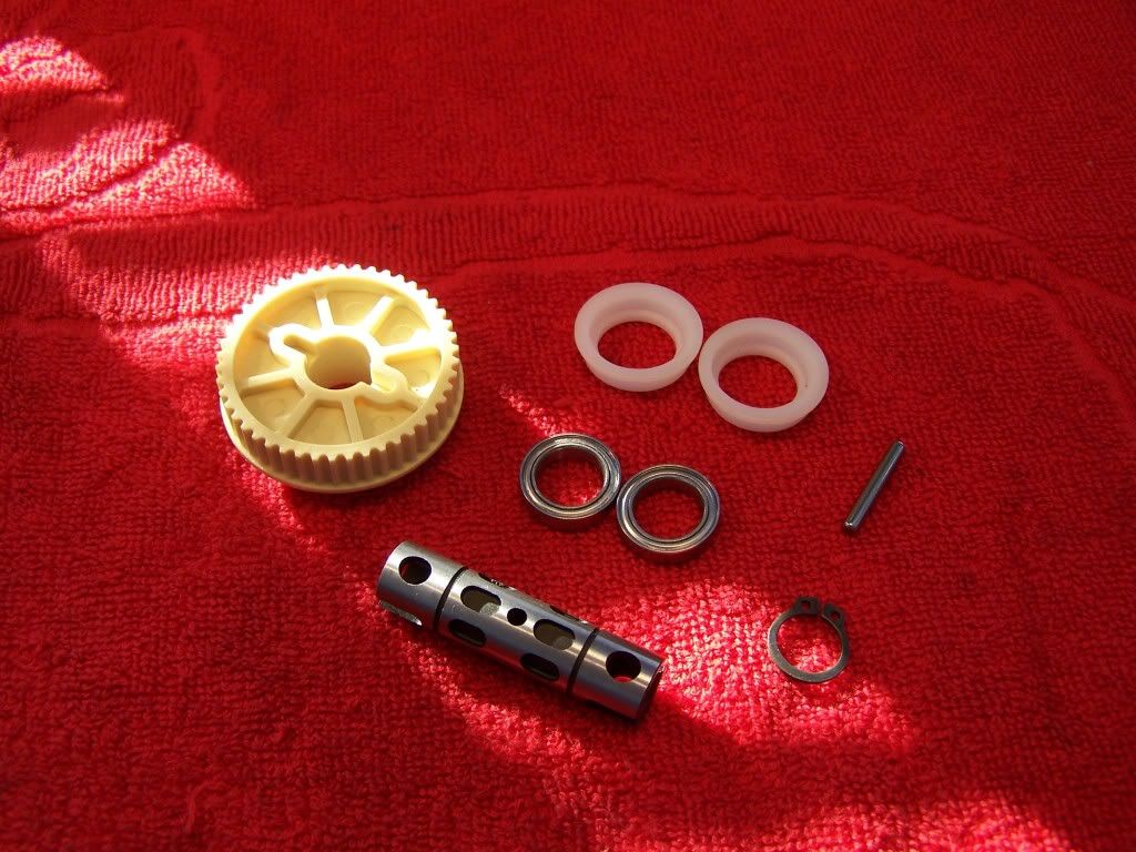
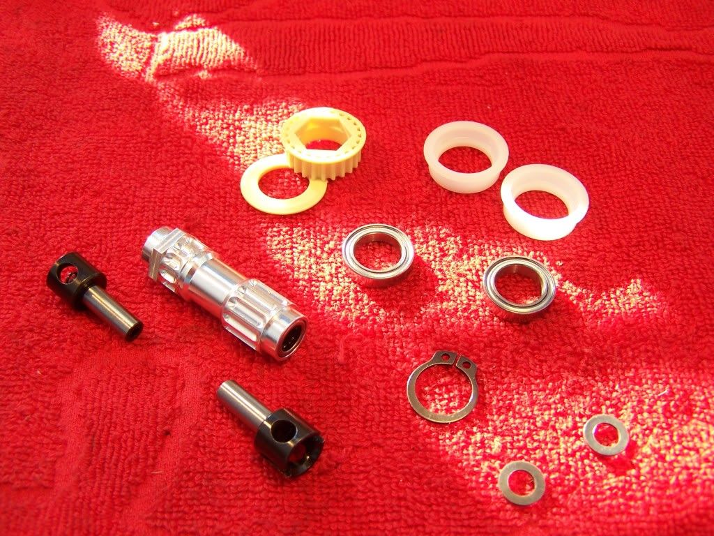
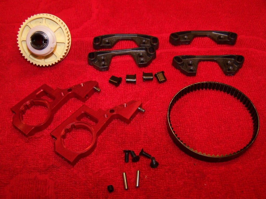
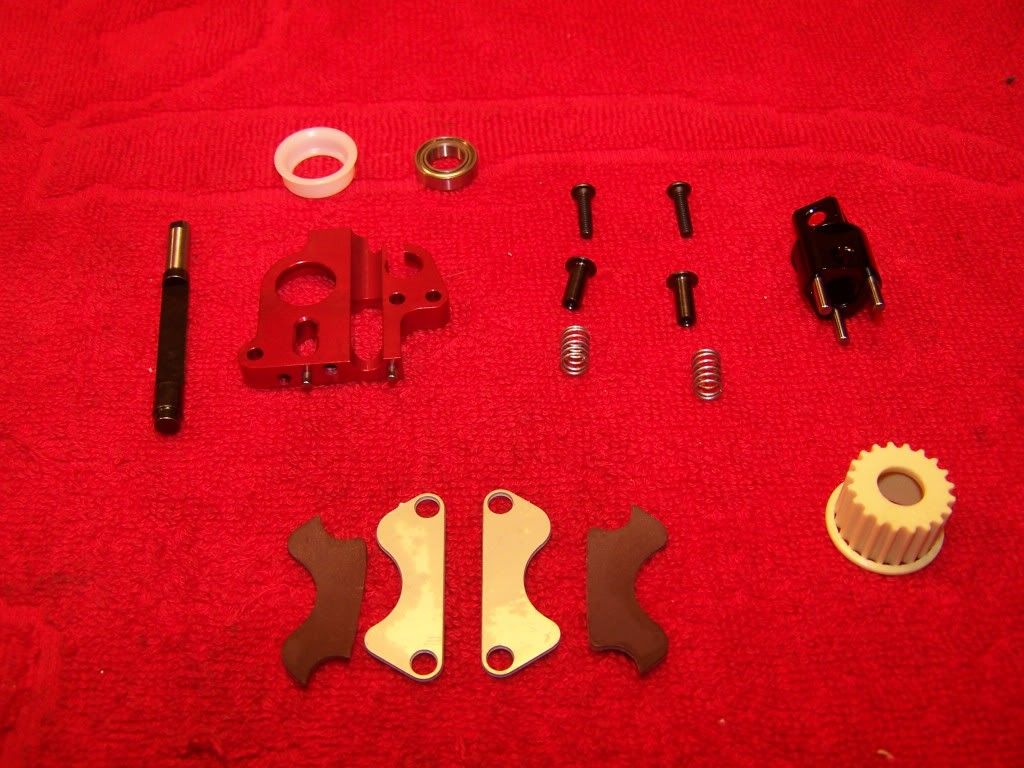
Parts for the gearbox:
It's important to remove the flashings from the two speed shoes before assembling them. I also first screw the first two shoes together without mounting them to the axle and sand both sides of the shoes to make sure they are perfectly flat.
It's advised to tighten the two speed setting screws fully and then back them out three full turns.
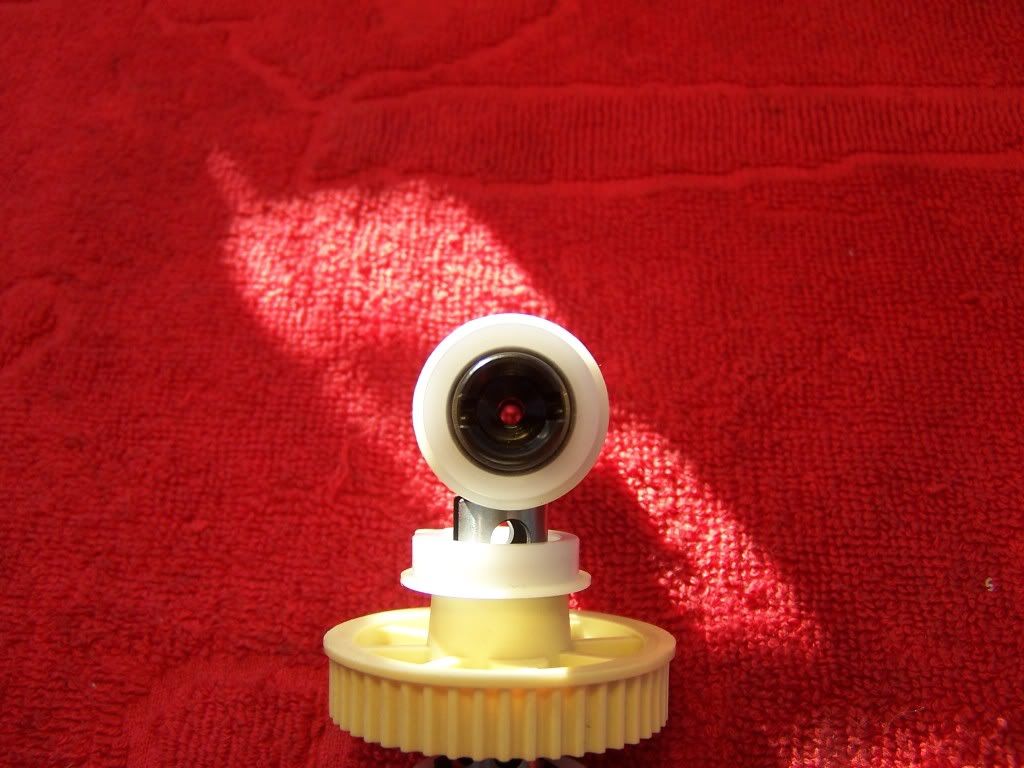
Assembled shoes:
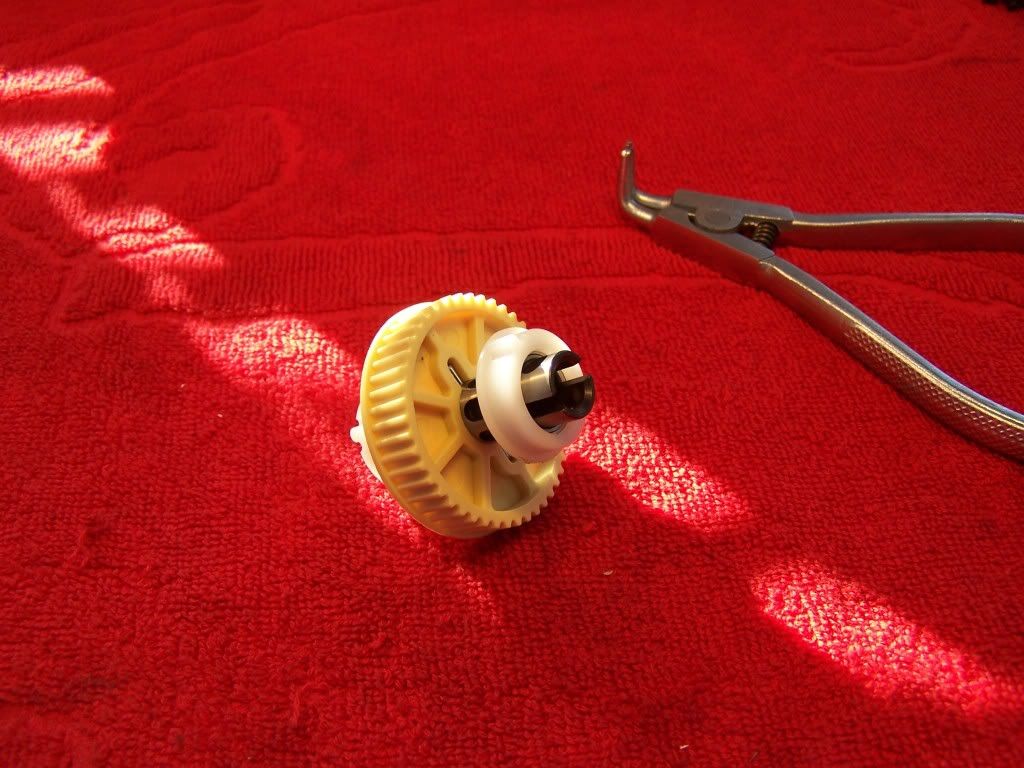
Gears and carriers:
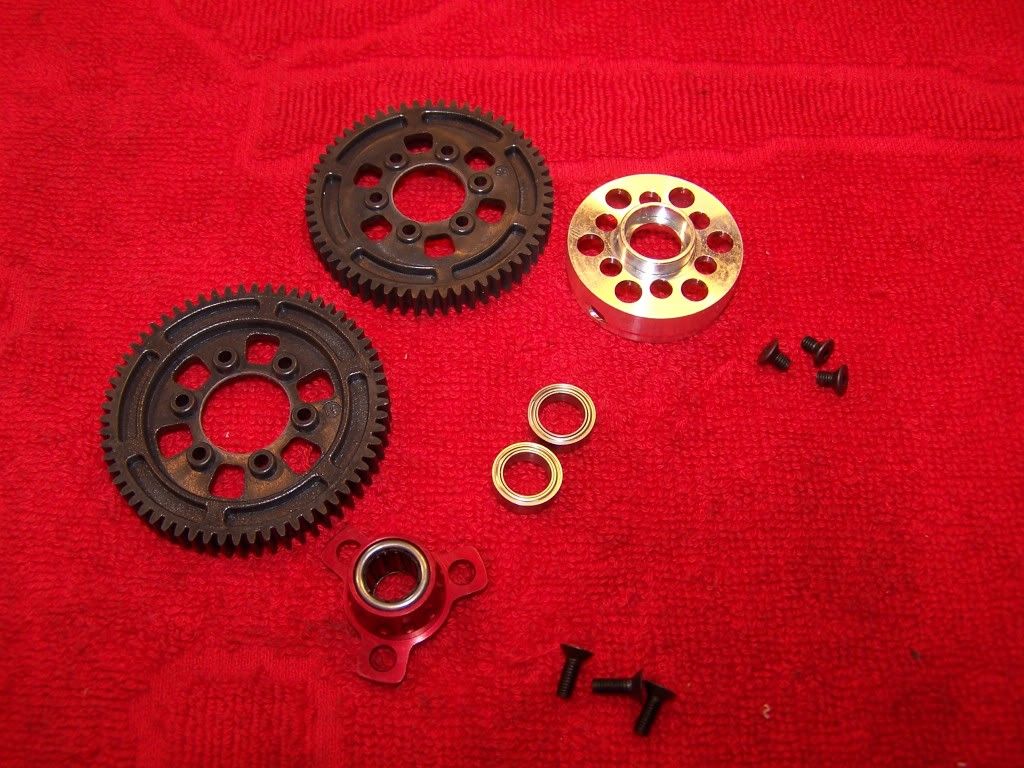
Fully lightened carriers to reduce the rotating mass as much as possible.
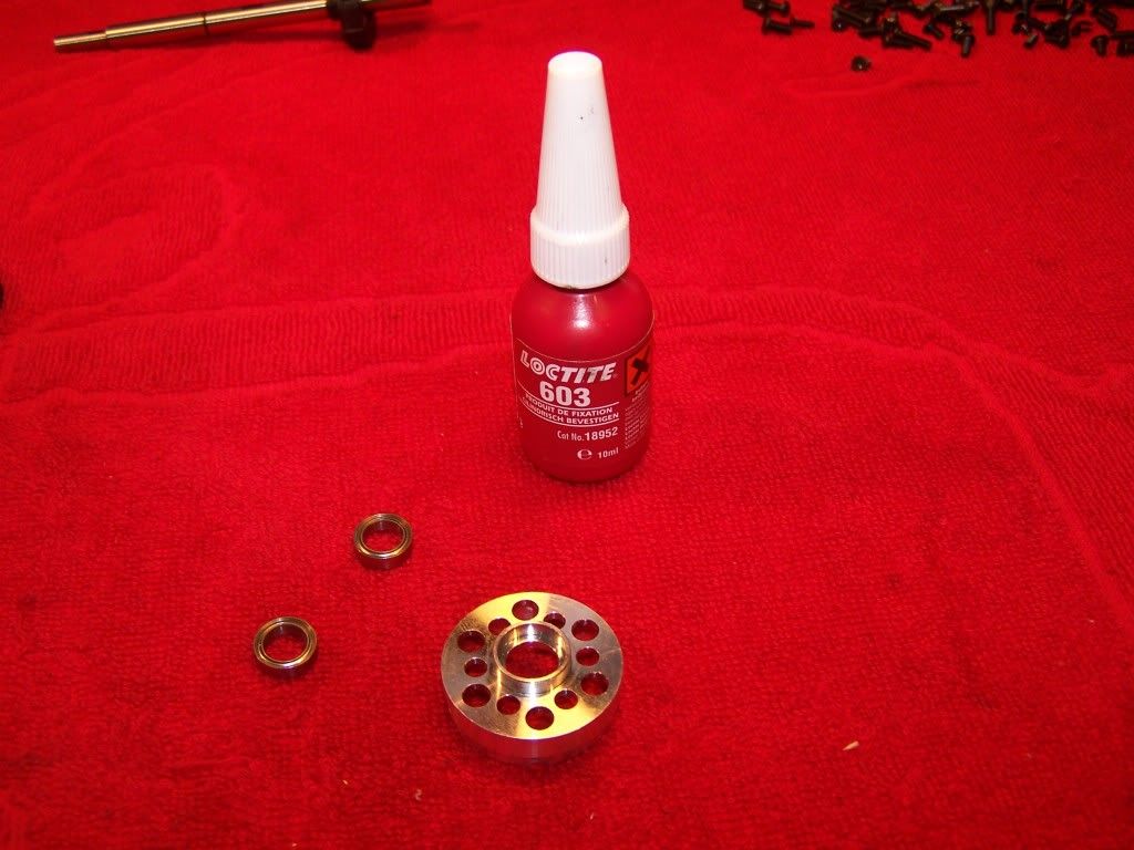
I like to use Loctite 603 (Bearing fit) to make sure the bearings are secured in the two speed drum. A small drop per bearing is enough to secure them, make sure nothing gets into the bearing, the fluid is very thin and will lock up the bearing. When you want to replace the bearing just use a little heat and they will come out quite easily.
For some reason I forgot to take a picture of the fully assembled gearbox.
Step 6, Servo saver
Parts for the servo saver:
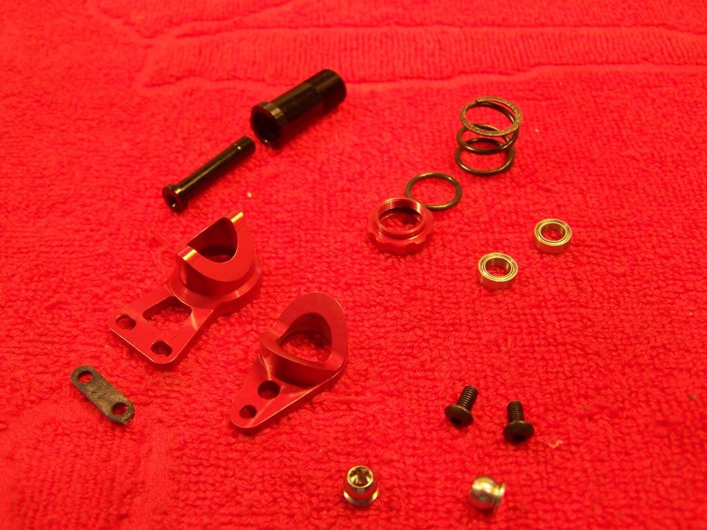
The servo saver is an all aluminum piece which has different inserts for changing the ackermann settings.
Assembled servo saver:
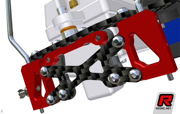
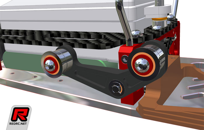
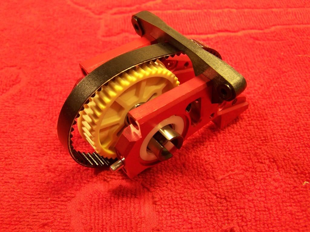
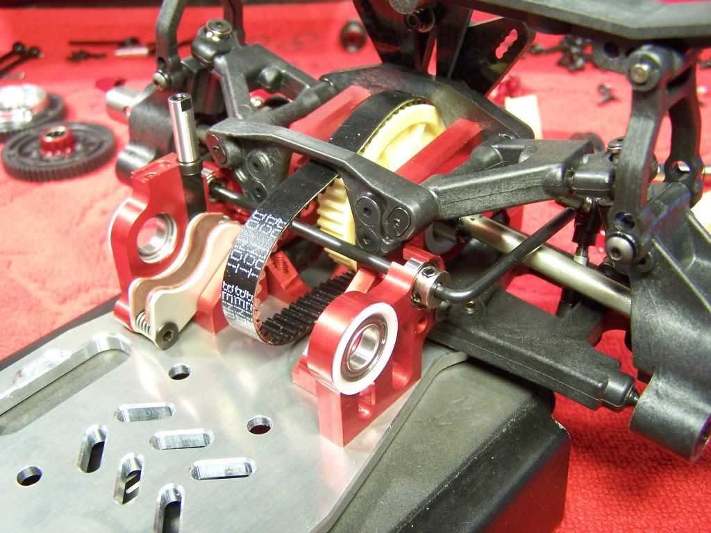
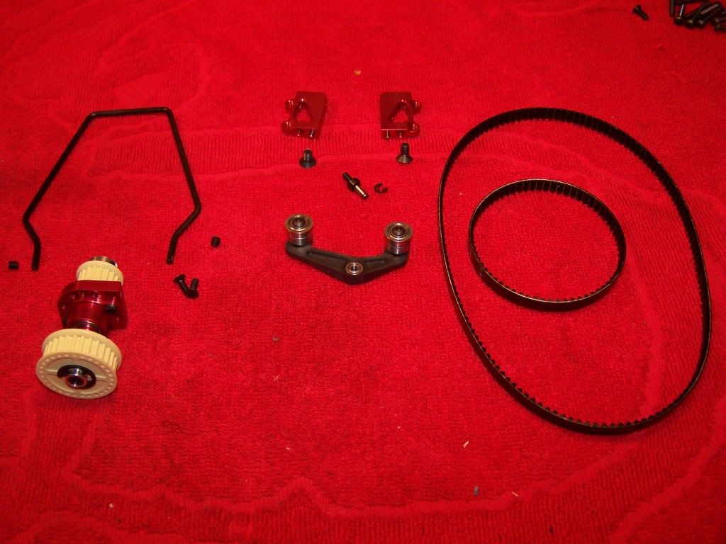
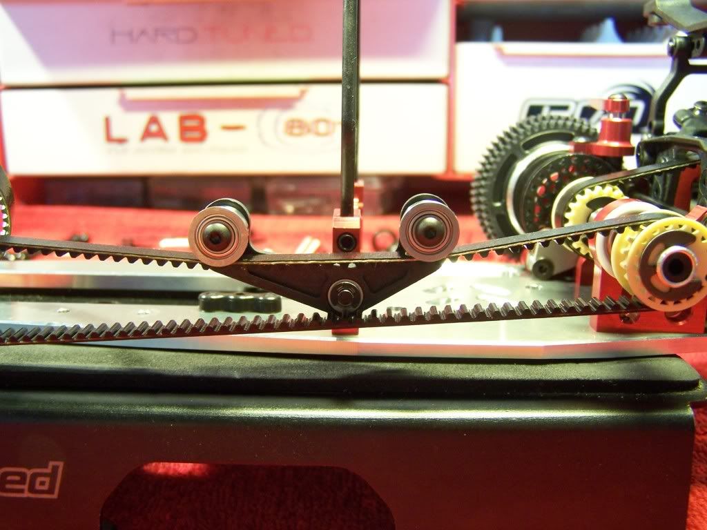
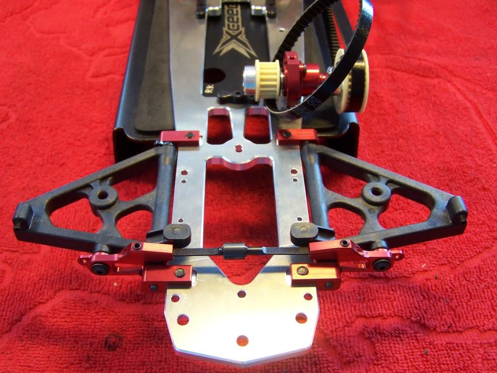
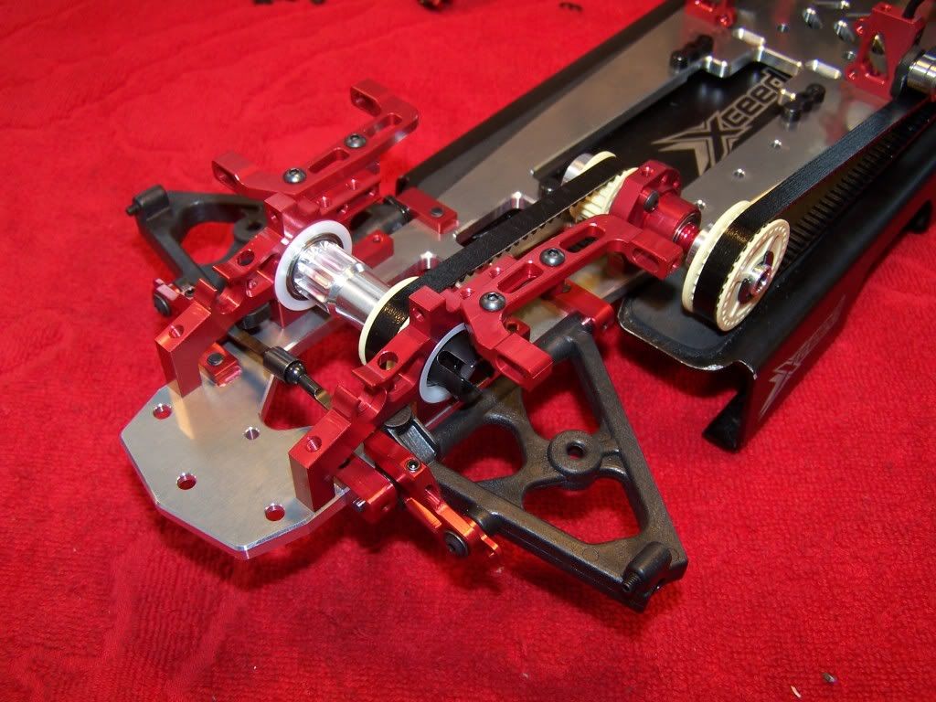
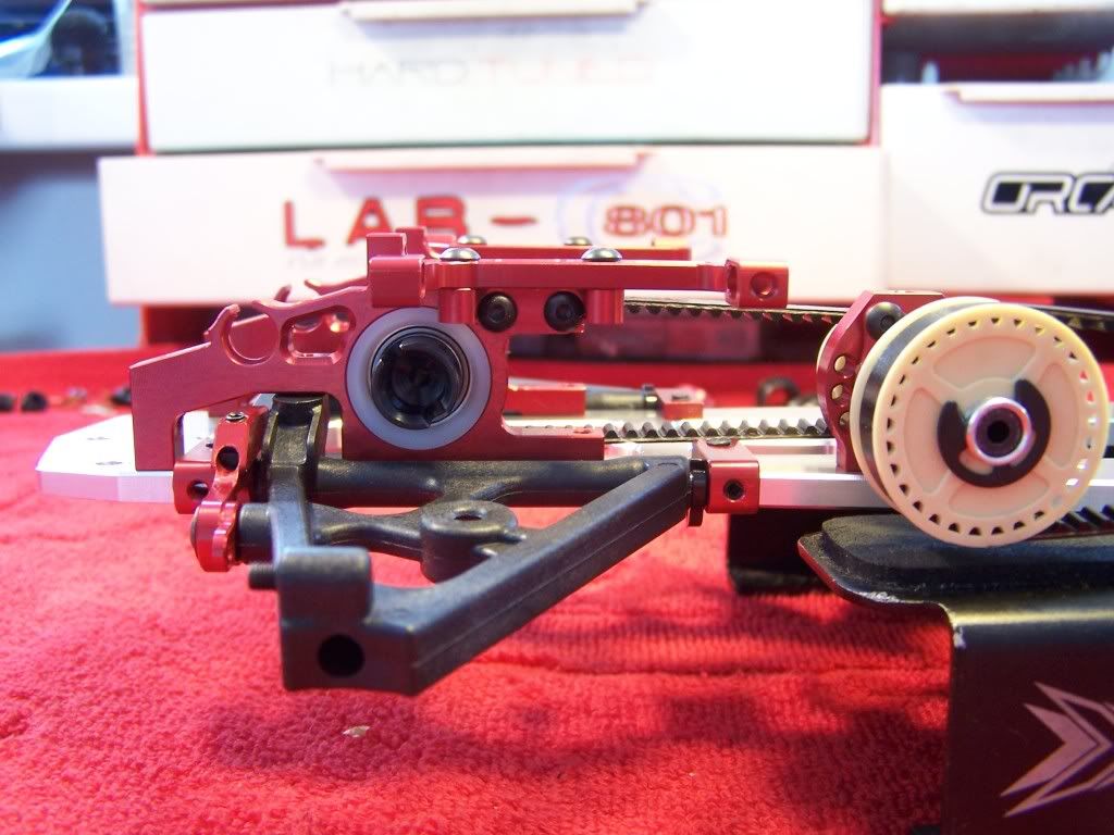
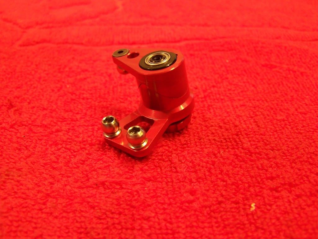 Step 7, Side Belt tensioner
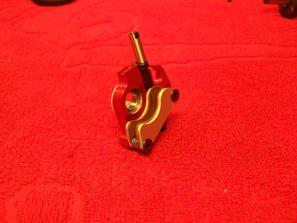
Parts for the Belt tensioner:
This is one of the outstanding features of the C801. The floating belt tensioner reduces the drag dramatically while having the belt wrap around the pulleys better.
Assembled tensioner:
 Step 8, Rear suspension
Parts for the rear hubs:
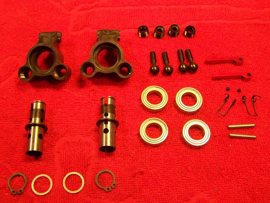
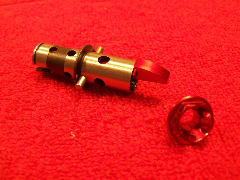
The wheel axles come fully lightened as standard and are secured in the bearings by clips. The kit comes with the regular quick release system but because the wheel axles are threaded it's also possible to use wheel nuts instead:
Make sure you use the short pivot ball nuts on the rear hubs.
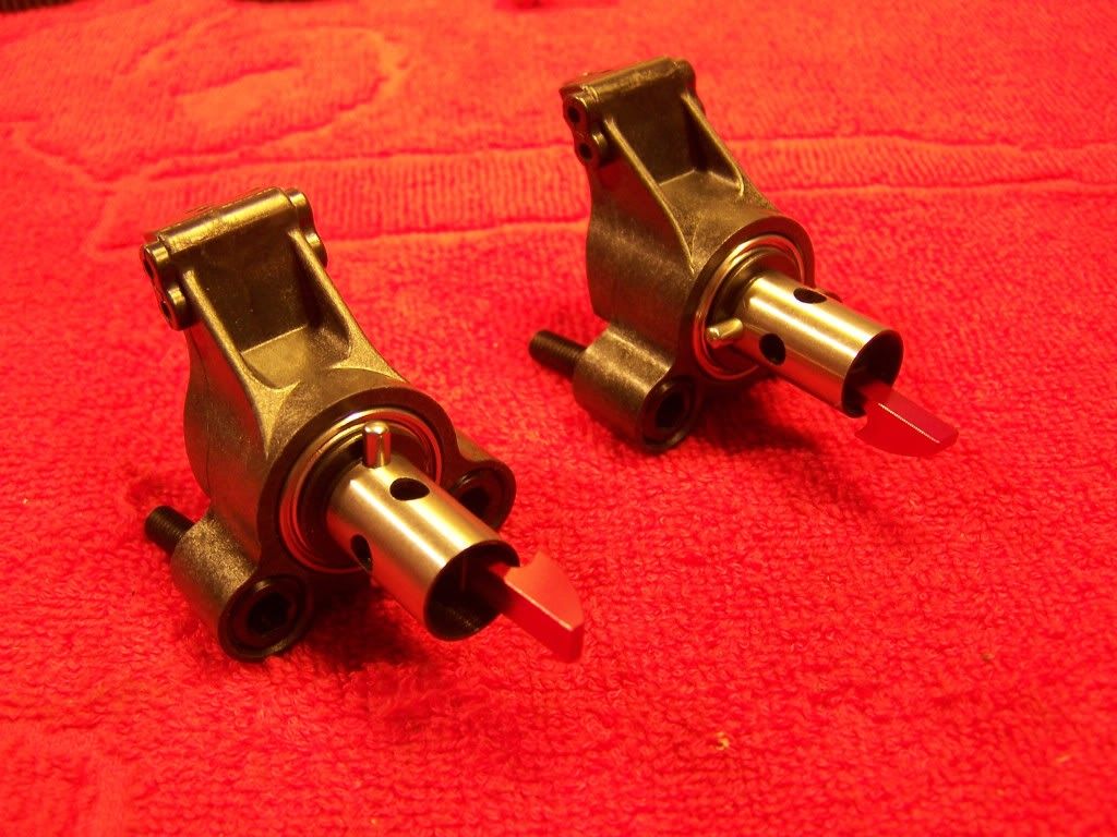
Assembled rear hubs:
 Step 8.1 Rear suspension
Parts for step 8.1:
Two different roll centre bridges are supplied with the kit, a angled one (type A) and a straight one (type B). I would advice to build the car with type B as this gives you the ability to only change the roll center height.
Also I would advice to set the belt in it's most loose position, the standard position is a bit too tight for a new kit. After a couple of days of running the eccenter can be put back in the middle position.
For the pins which need to be glued in I would also recommend using Loctite 603, a drop is enough. Any excess glue needs to be wiped off.
Rear bulkhead assembly:
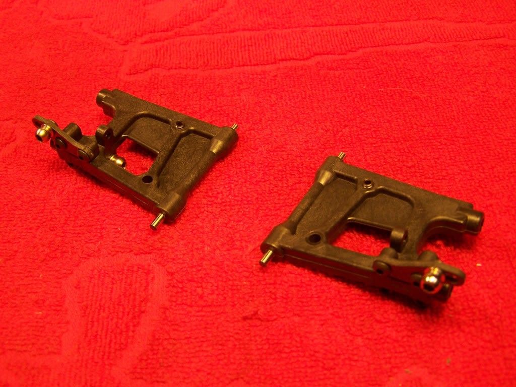
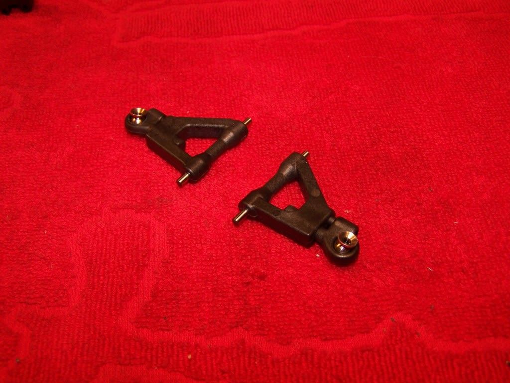
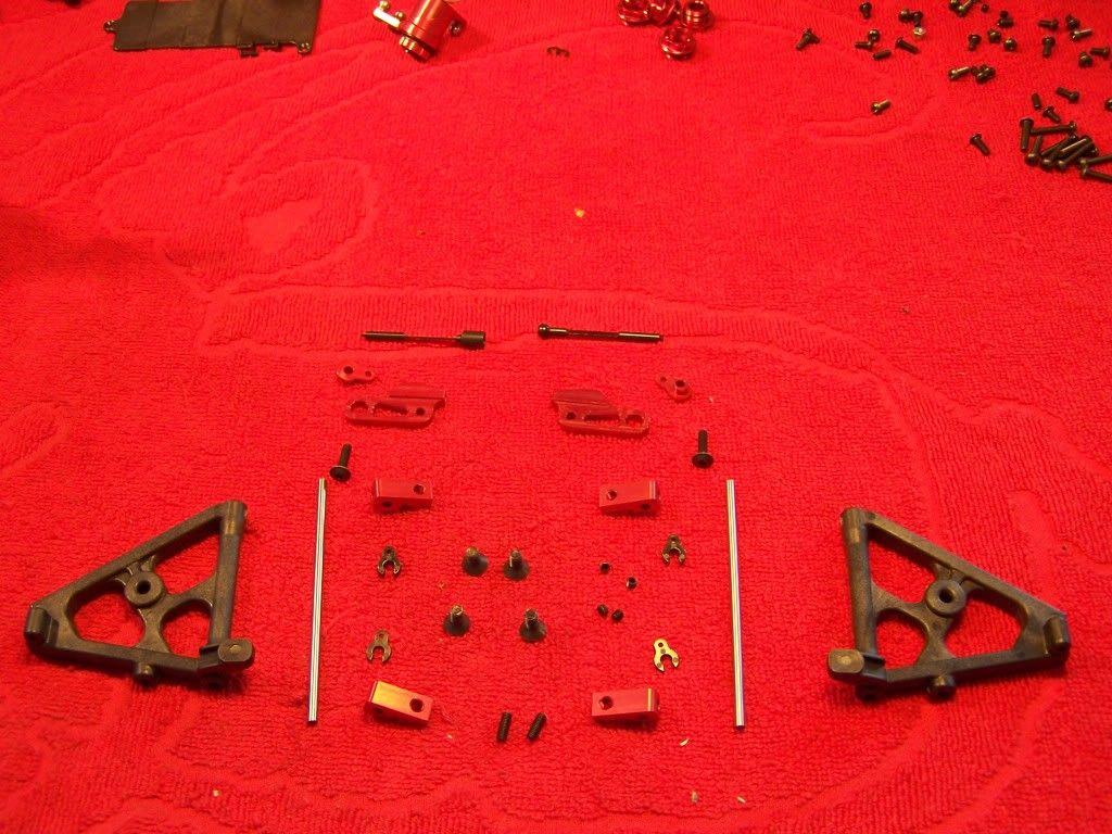
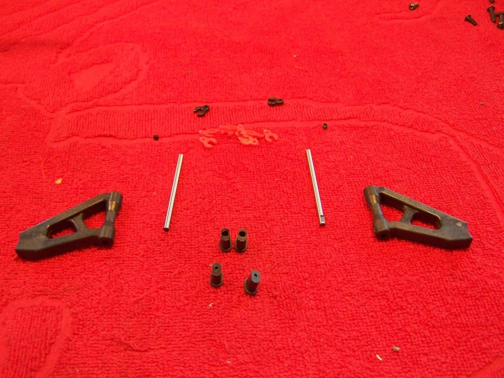
 Step 8.2, Rear lower wishbones
Parts:
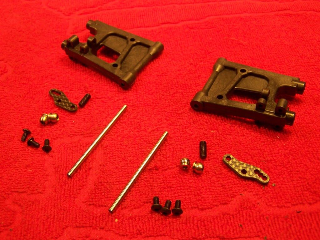
You might use a reamer to make sure that the wishbone rotates smoothly over the pin.
Assembled lower wishbones:
 Step 8.3 Rear upper wishbones
Parts:
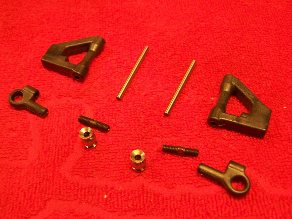
The rear upper wishbones also have an outstanding feature, they don't use a standard turnbuckle to adjust their length but it's possible to adjust it with a 2mm allen key. This gives you the ability to change the camber very quickly in the pits. Having correct camber settings is very important for optimal performance and this feature makes it possible to dial in your camber settings during a heat.
Assembled rear upper wishbones:
 Step 8.4, Sub assembly
Parts:
Make sure the upper arms move freely, they don't have to fall down under their own weight but they should rotate without a lot of resistance.
Assembled parts:
 Step 8.5, Rear bulkhead
Parts:
First make sure the glue for the pins from step 8.1 has fully dried, otherwise you might run into problems later when you want to disassemble the parts.
Mount all the parts to the chassis, but don't fully tighten all the screws yet.
Once all the parts are mounted tighten the bottom screws first and the the M3 sized screws. This makes sure all the parts are aligned properly.
Check if the arms can move freely, they don't have to fall down under their own weight but should rotate without much resistance.
Assembled parts:
 Step 8.6, Mounting rear hubs
Parts:
Make sure to screw in the pivot balls straight into the lower wishbones, otherwise they might cause binding. I always put a small dab of copper grease on the threads of the pivot balls to help them create a clean thread into the wishbones.
For the dog bones I like using Capricorn blue grease or Hudy graphite grease. Never use oil for lubricating the driveshafts as it will run into the bearings taking any dust or sand with it.
When you have assembled the rear end make sure it falls down under it's own weight, when it doesn't check the following:
-Pivotball retaining nuts, there should be a tiny amount of play between them and the pivot balls
-Slightly undo the four M3x12 screws retaining the back cover, if this unbinds the suspension you will have to sand down or ream the lower wishbones.
-Ream or sand down the upper wishbones.
-Check if the uniball of the upper wishbone is screwed straight into the rear hub.
After checking this the suspension should move freely, but without any play.
Assembled parts:
 Step 8.7 Rear body support
Parts:
After assembling the rear body support make sure the suspension still moves freely.
For more wheel travel and the ability to mount the body higher you will need the optional long carbon guide.
The body posts are eccentric which gives you the ability to move the body back and forth.
Assembly:
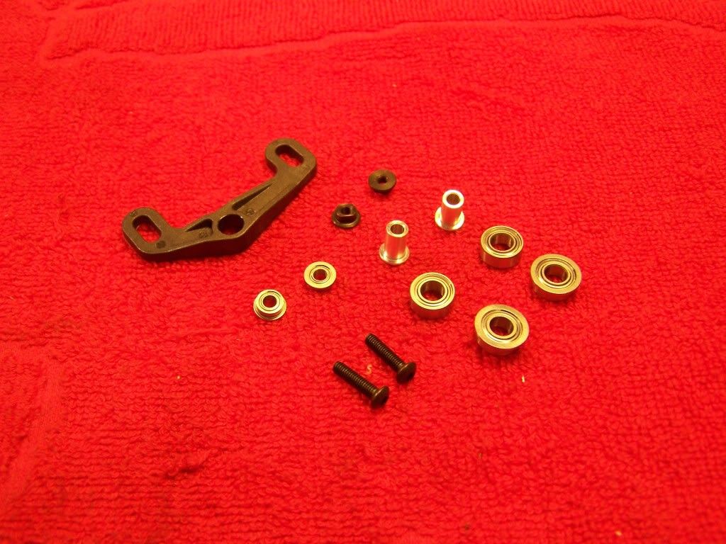
 Step 9 Brake system
Parts:
The brake pads are moving on smooth bushings and have springs in between them to ensure a smooth engagement and disengagement of the braking system.
Before gluing the pads you will need to sand the steel plates to make sure the glue sticks. You can either use some 80 grit sand paper or a dremel with rough the sanding drum. I glue the pads with Bison Tix, with this I know the pads aren't affected by the glue and the pads don't come undone even in very high temperature. Some aggressive epoxy glues can harm the pads.
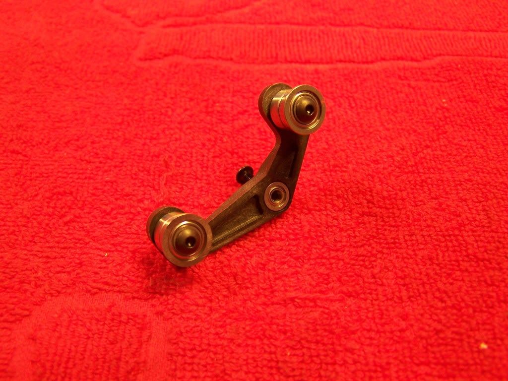
Coat both the pad and the steel plate with a thin layer of glue and let them dry for 15 minutes. After that press them together firmly by putting the pads in a vise or a frame clamp and let the glue fully dry for 24 hours.
Assembled braking system:
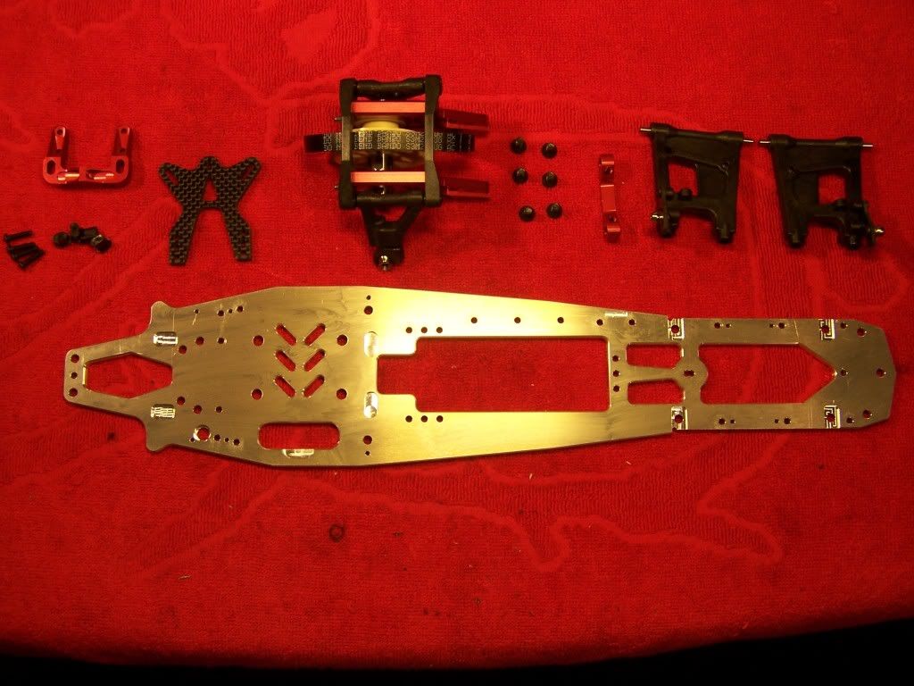
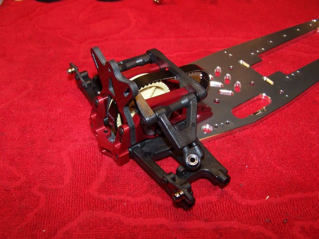
 Step 9.1 Rear transmission
Parts:
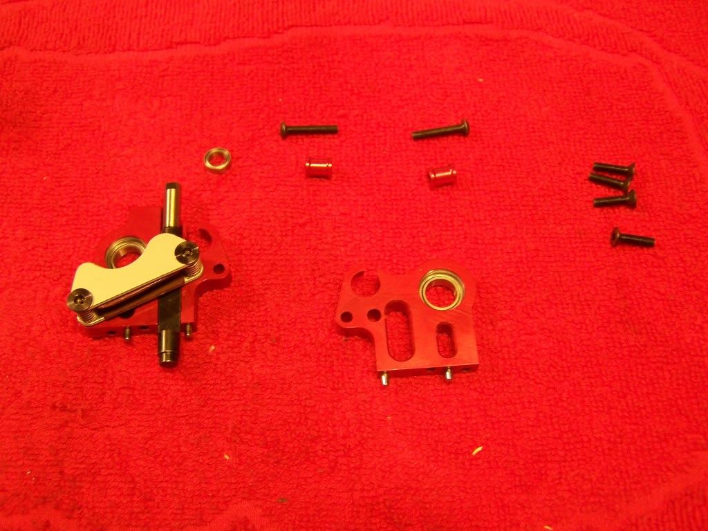
First put the small bearing into the chassis.
Then mount all the parts to the chassis but don't tighten up the screws fully.
After all the parts are mounted tighten up the bottom screws and then the two M3x16 screws.
The M4 grub screw in the rear bulkheads is used for setting the play between the brake pads and brake disk.
Assembly:
 Step 9.2 and 9.3 Rear anti rollbar and two speed axle
Parts:
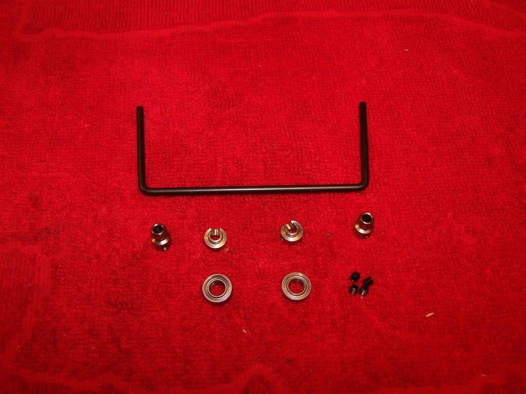
Standard the car comes with a 3mm ball raced anti roll bar. A 3.2mm one is available seperately.
Make sure the anti rollbar is centered and can move freely
Make sure the two speed axle has a small amount of play, around 0.2mm.
Assembly:
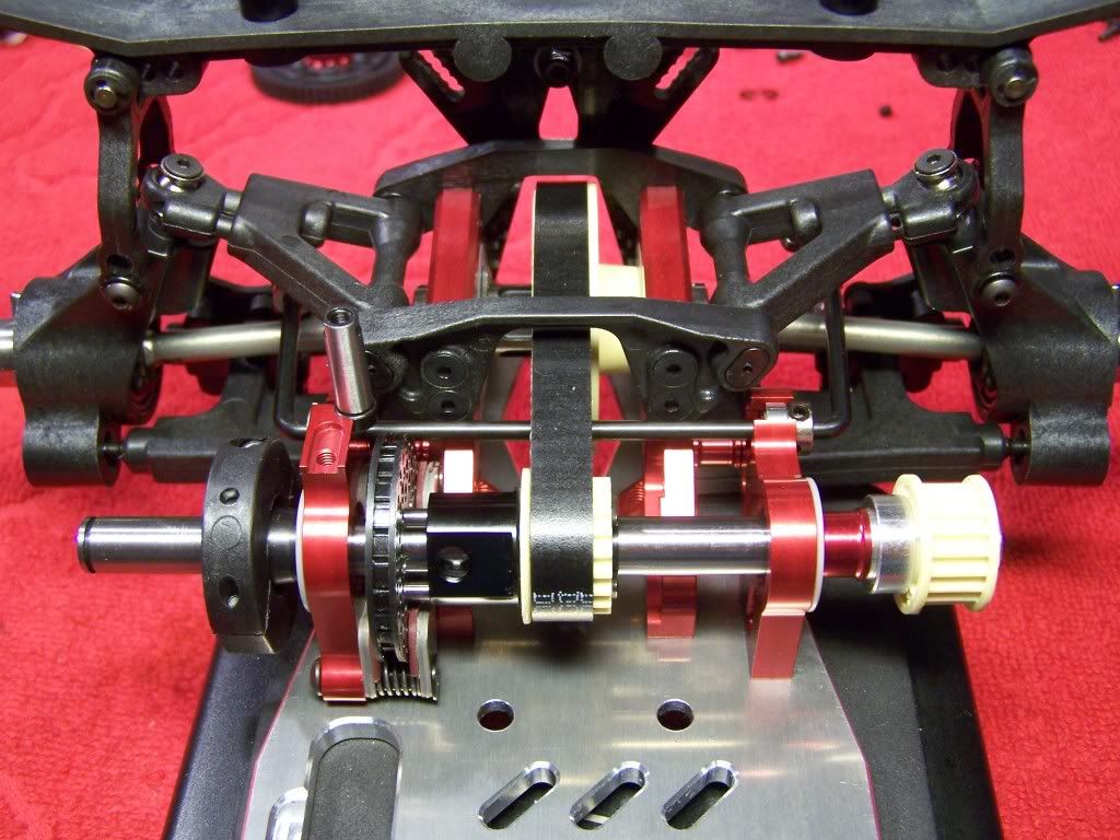
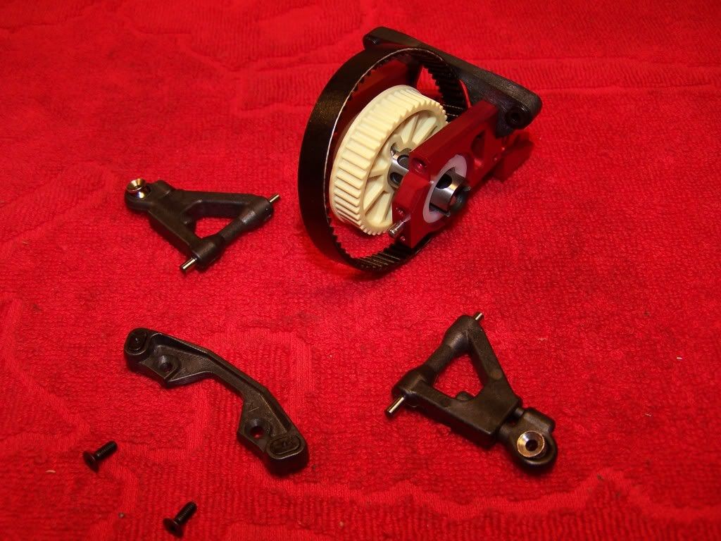
 Step 9.4/10 Two speed gears and battery tray
Parts:
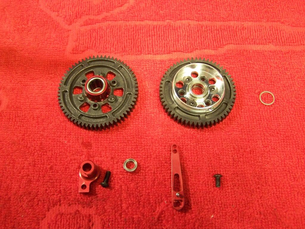
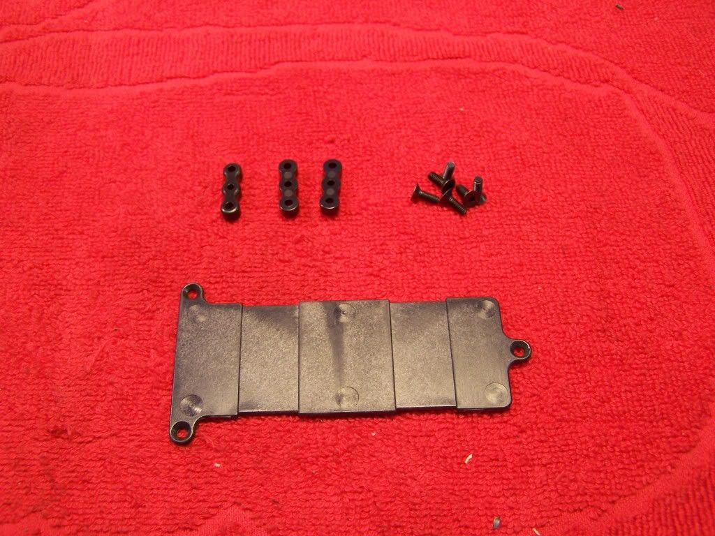
Make sure the gears can rotate freely and lube the one way bearing with some oneway oil.
With the kit comes a plastic tray, optionally there is a carbon or brass tray available. The carbon tray will reduce flex and the brass tray will add weight.
Assembled parts:
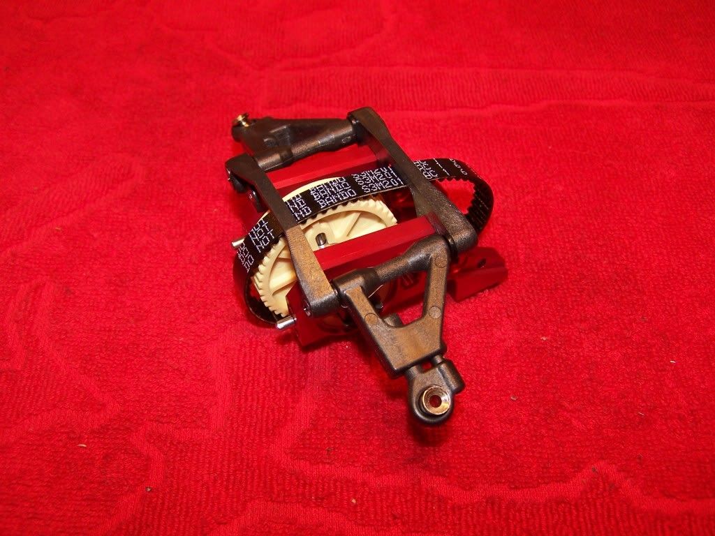
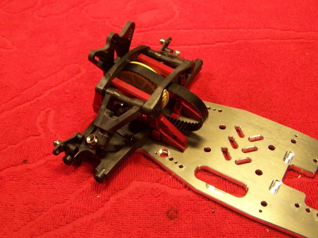
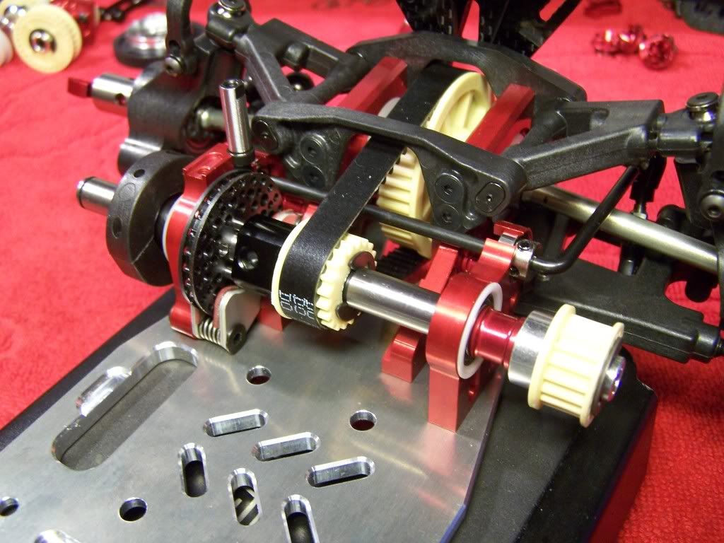
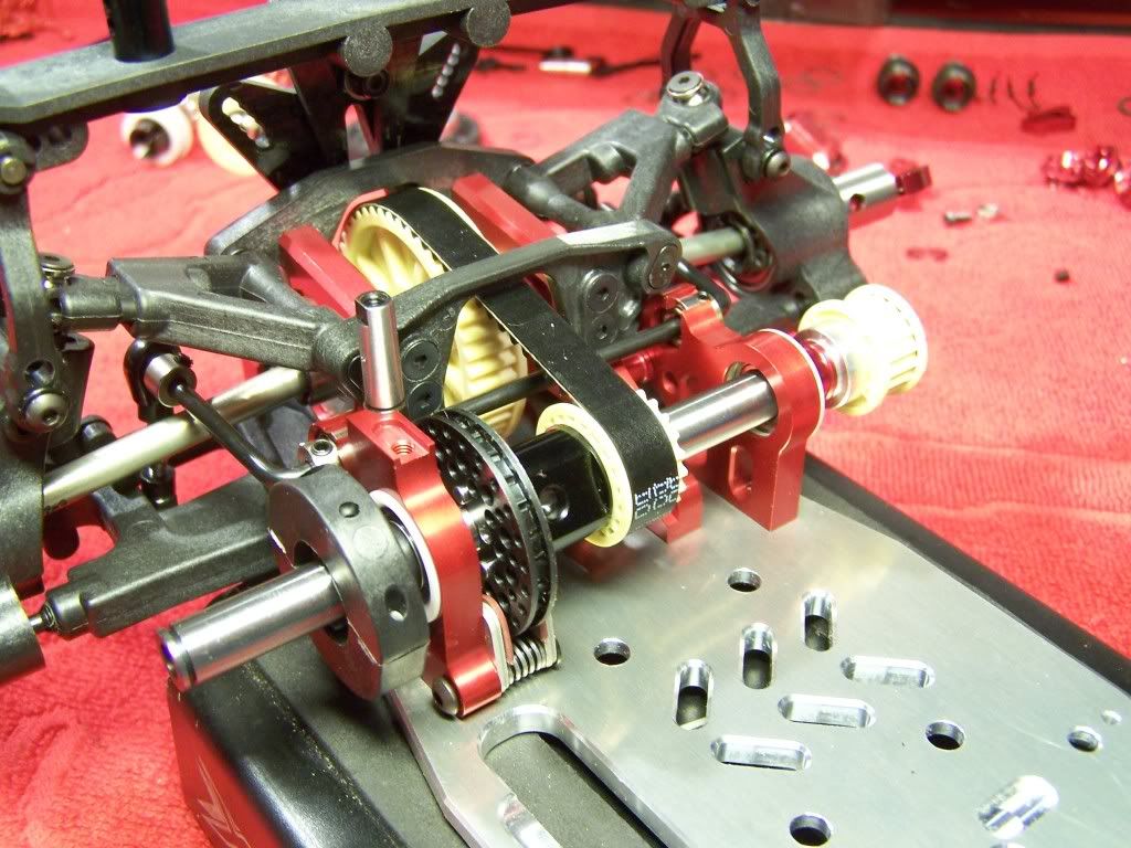
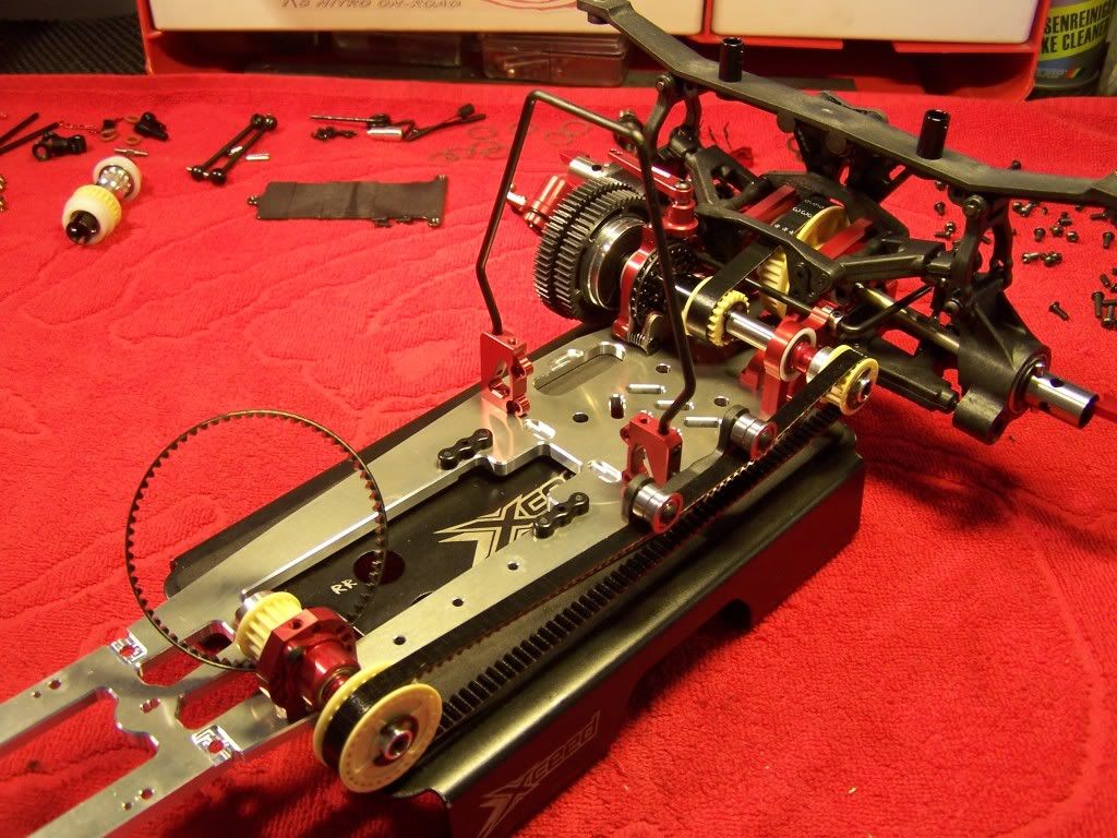
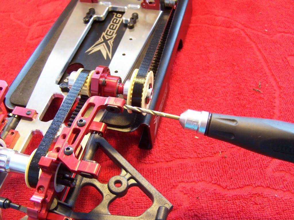
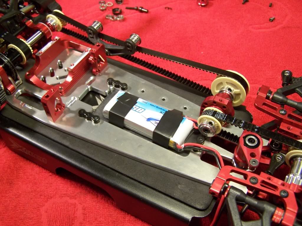
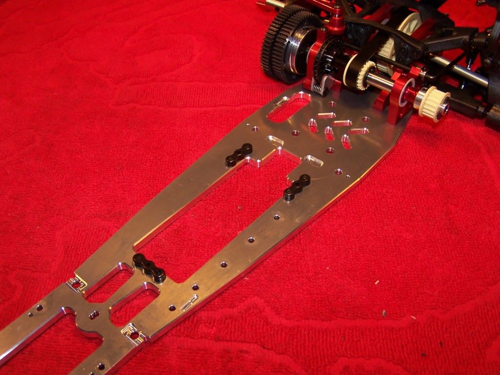 Step 11 Central transmission
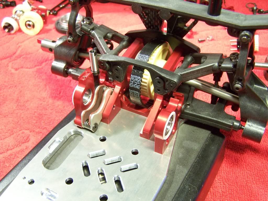
Parts:
Make sure to take off some material from the battery tray mount as shown in the manual to make sure the pulley can rotate freely.
After mounting all the parts you can set the side belt tension. The amount of belt tension is a personal preference but I like the upper and lower teeth of the belt just able to touch around the center of the belt when you press down on it.
Assembly:
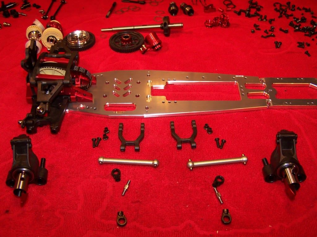
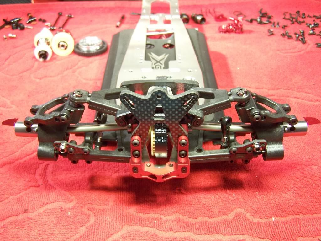
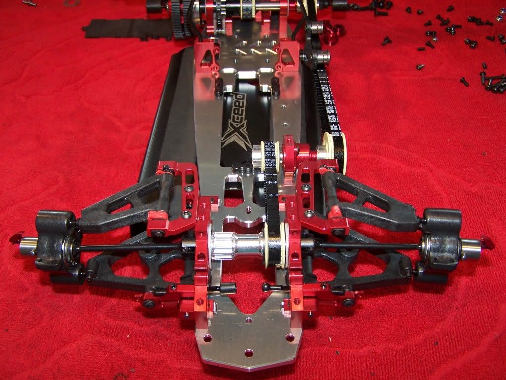
 Step 12 Front suspension
Parts:
Make sure the lower wishbones are able to move freely.
The kit comes with a blade style front stabilizer, optionally there is a ball raced wire stabilizer available.
Assembly:
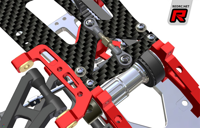
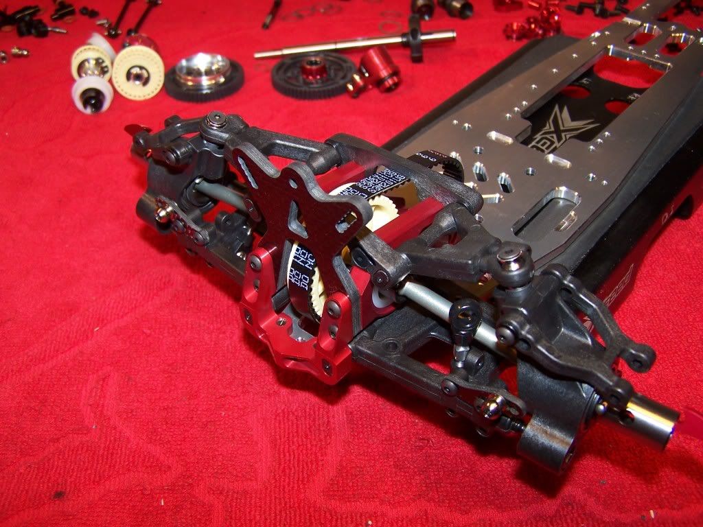
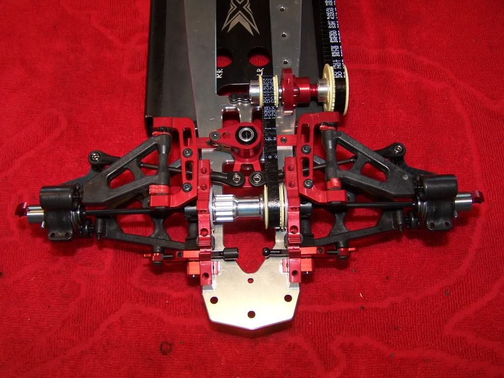
 Step 12.1 Front transmission
Parts:
Make sure the delrin bearing bushings are seated into the bulkheads fully as they might cause binding otherwise.
After everything is mounted to the chassis you can set front belt tension by adjusting the middle axle mount eccenter.
Assembly:
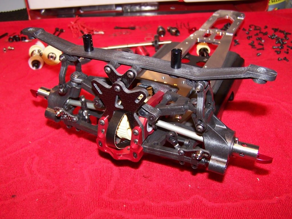
 Step 12.2 Front upper bulkheads
Parts:
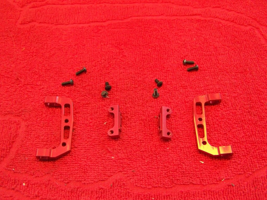
The construction of the upper bulkhead makes it very easy to change rollcentre settings or taking out the front driveshafts.
Assembly:
 Step 12.3 Front suspension
Parts:
The roll centre inserts need to be drilled before mounting, the front one needs to be drilled with a 3mm drill and the back one with a 1,5 or 2mm drill. I prefer to drill the back one with a 2mm drill because it makes it easier to push out the suspension pin.
I prefer to drill them by hand because this gives a much better cut. I use a new drill bit mounted into a Hudy screwdriver handle. After drilling the inserts make sure there aren't any debris left as this might cause the suspension to bind.
After mounting the roll centre inserts into the upper bulkheads the rear rollcentre inserts need to be drilled through the side with a 2,5mm drill:
Make sure there aren't any flashings left.
Then mount the wishbones and make sure they move freely, if they don't sand and ream the wishbones.
Assembly:
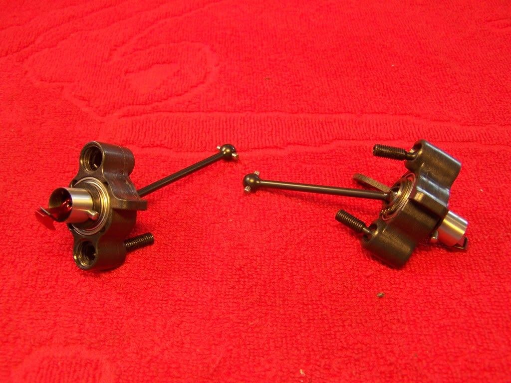
 Step 12.4 Front uprights
Parts:
Assemble the front cvd's with either Capricorn blue grease or Hudy graphite grease. I don't like using the small grub screw which retains the pin as I think it binds of the assembly.
CVD's:
Make sure you have both uprights assembled the same way, they have an kingpin inclination build into them. The longer side needs to towards the top for the stock setting.
Screw the pivot balls straight into the wishbones and you might add a little copper grease to the threads to help cutting the threads.
Finally check if the suspension moves freely.
Assembly:
 Step 13 Steering system
Parts:
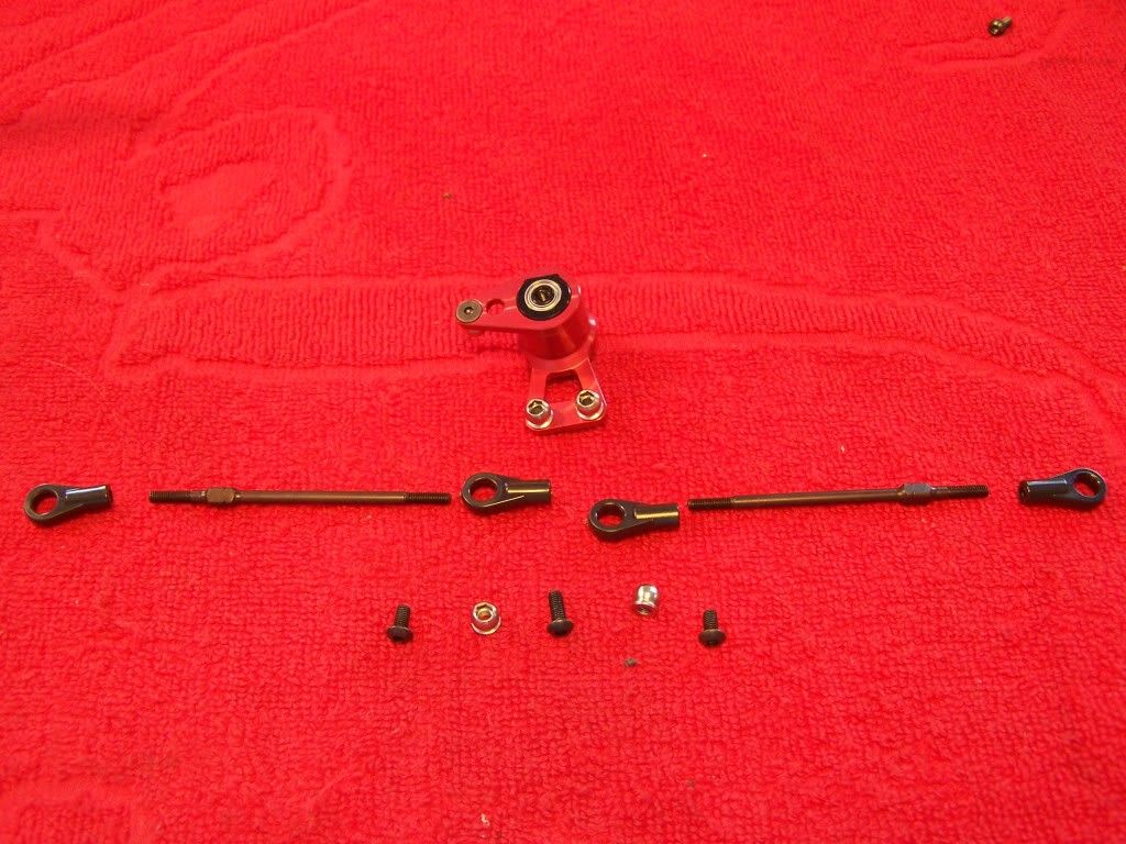
Make sure both track rods are the same length and after putting them on the car check if the suspension still moves freely.
If some of the ball ends are a bit tight pop the ball out and remove a small piece of material from the ball end.
Assembly:
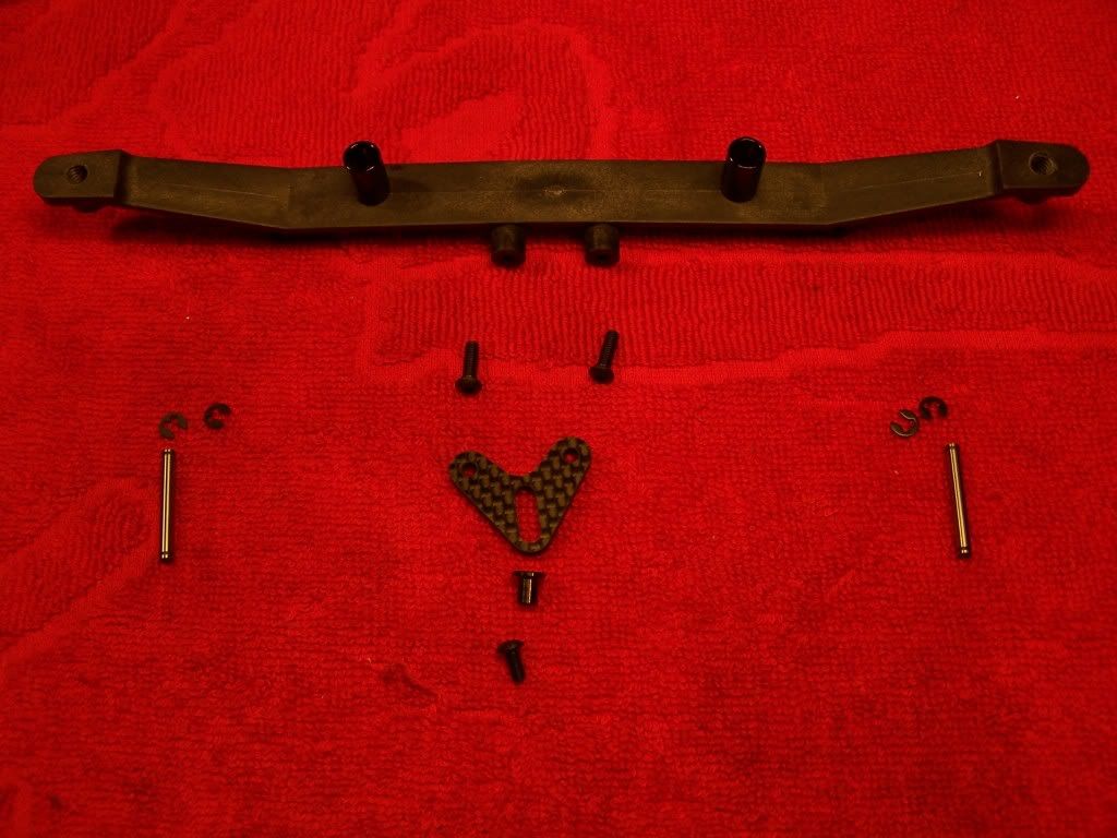
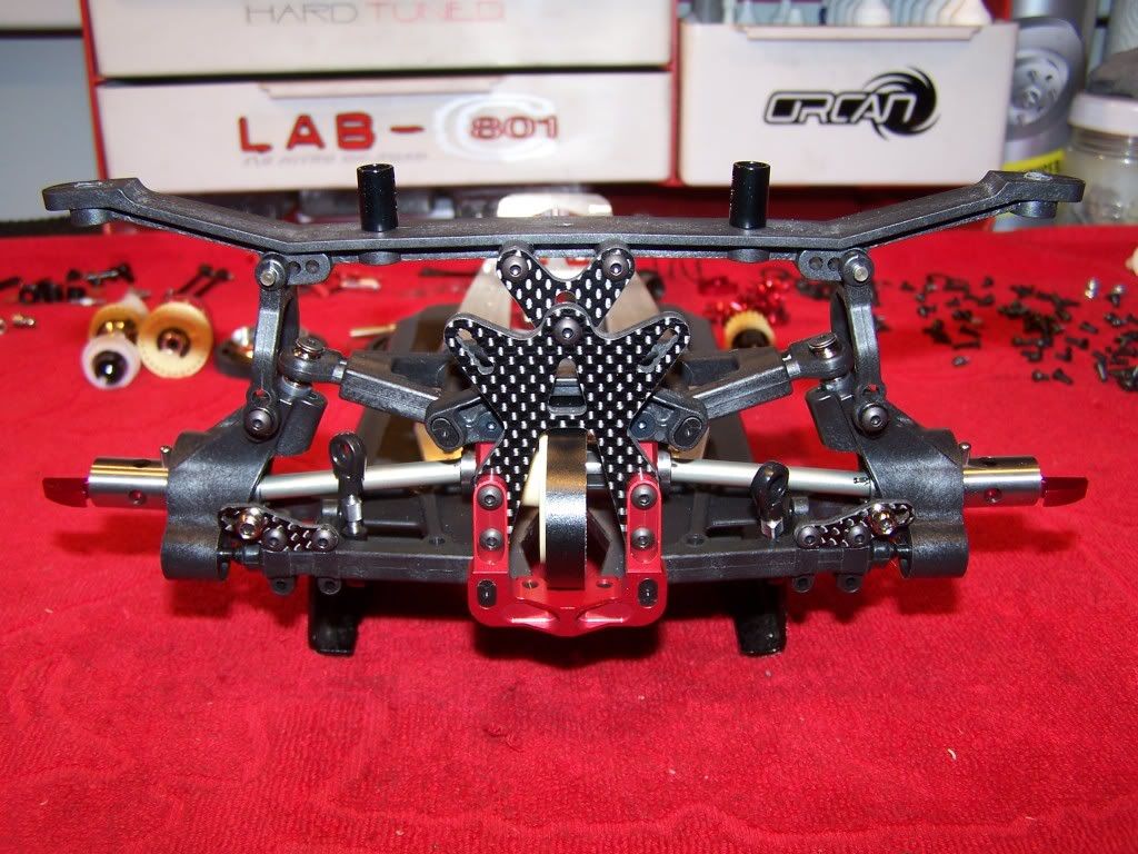
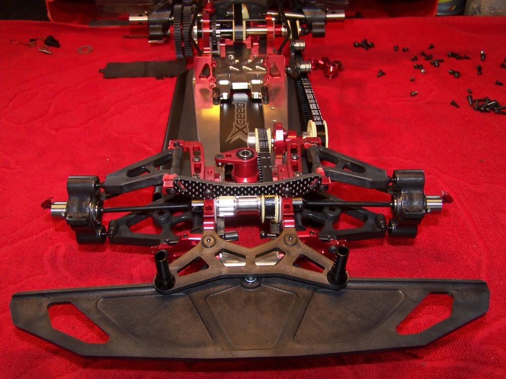
 Step 14/15 Front body mount and bumper
Parts:
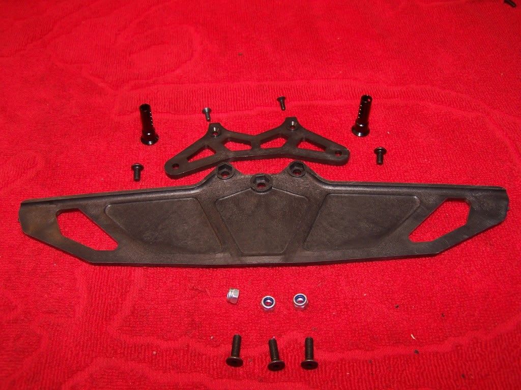
The body mounts are eccentric, so make sure to mount both in the same way.
Shocks will be mounted during setup.
Assembly:
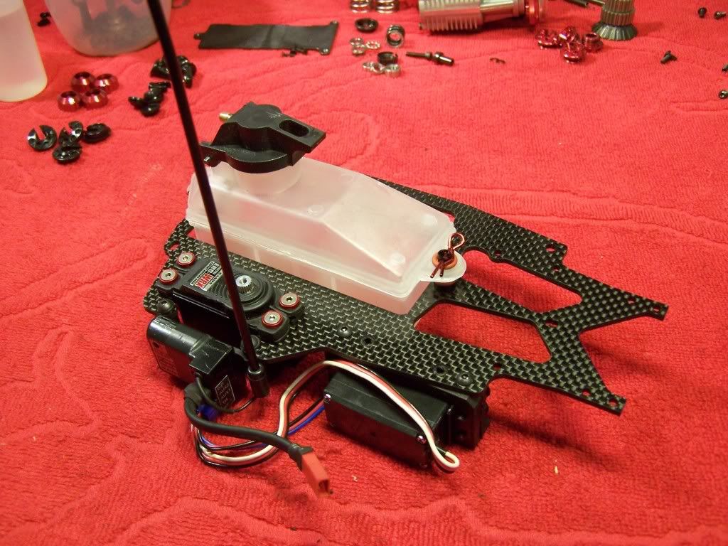
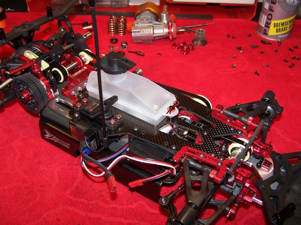
 Step 16 Fuel tank and electronics
The fuel tank cap might not fully seal when it's new. I've put a bit of fuel in the tank and put a rubber band over the tank cap and let it sit for a couple of days.
This causes the seal to swell and form itself to the tank which creates a perfect seal.
Adjust the tank height for the battery your using, try mounting it as low as possible.
I used two standard sized servos and the wiring still had to be shortened and shrink wrapped.
Servo horns aren't included so make sure you have some for the servos your going to use. I like using the aluminum 3racing horns since they are available in red which matches the car quite well, but I couldn't get them before the build so I had to settle with some plastics NT1 ones.
The battery is a 850Mah Lipo which I also use on my 1/10 car. In the 1/10 car it has enough capacity for 1 hour of driving. Don't know how long it lasts in a 1/8
I use the lipo without a regulator with normal servos, with the Futaba, Sanwa and Kopropo servos I use this isn't a problem.
Assembly:
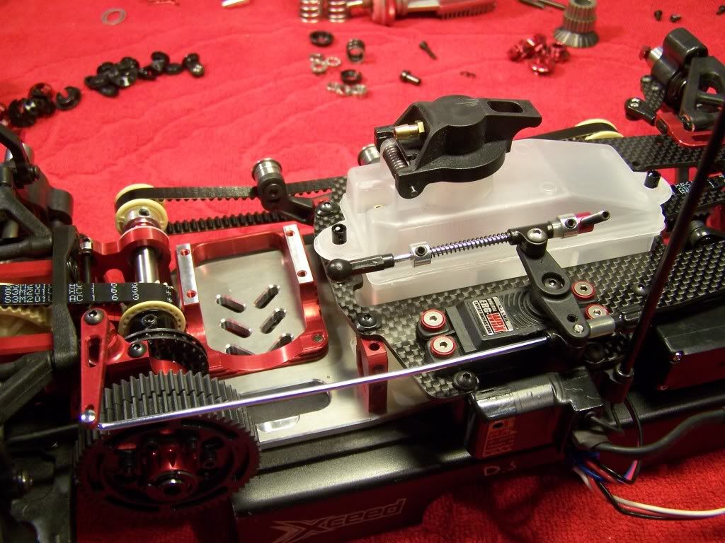
 Step 18 Gas/braking linkage
Parts:
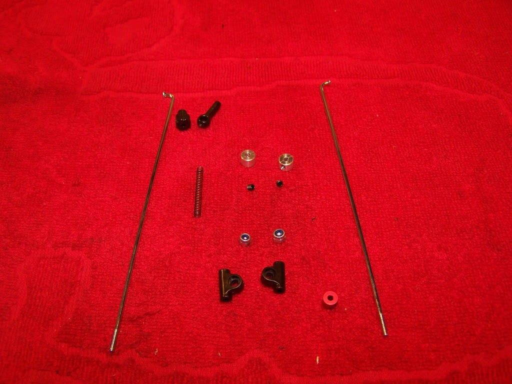
Bend the brake linkage as shown in the manual.
I'm not entirely happy with the linkage setup I ended up with, I like them to be mounted below the servo horn. When I will rebuild the car for the 2012 season I will try to come up with a better setup.
Assembly:
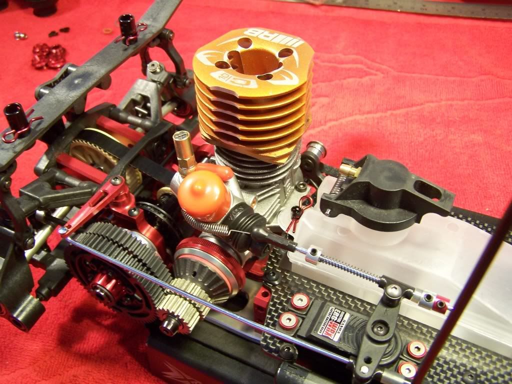
 Step 20 Clutch and motor assembly
Parts:
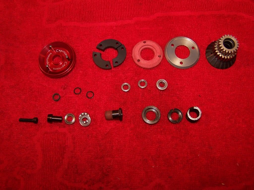
I will make a proper guid about building the clutch when I've got more experience with the 1/8 clutch. Right now I build it like the manual suggests.
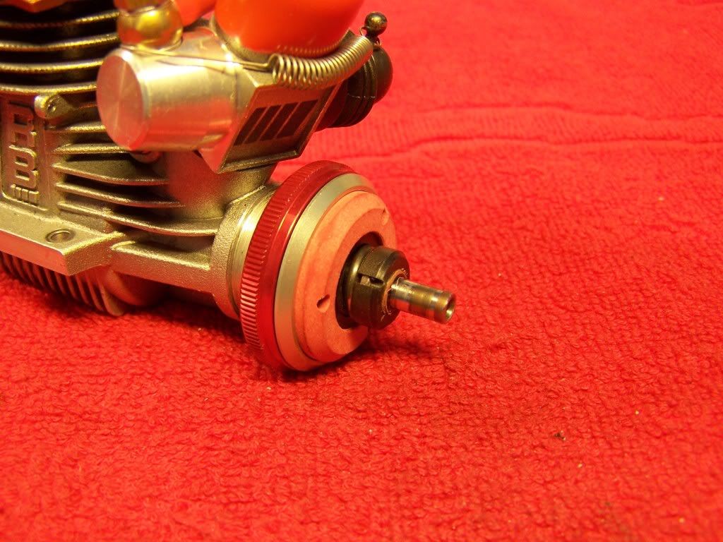
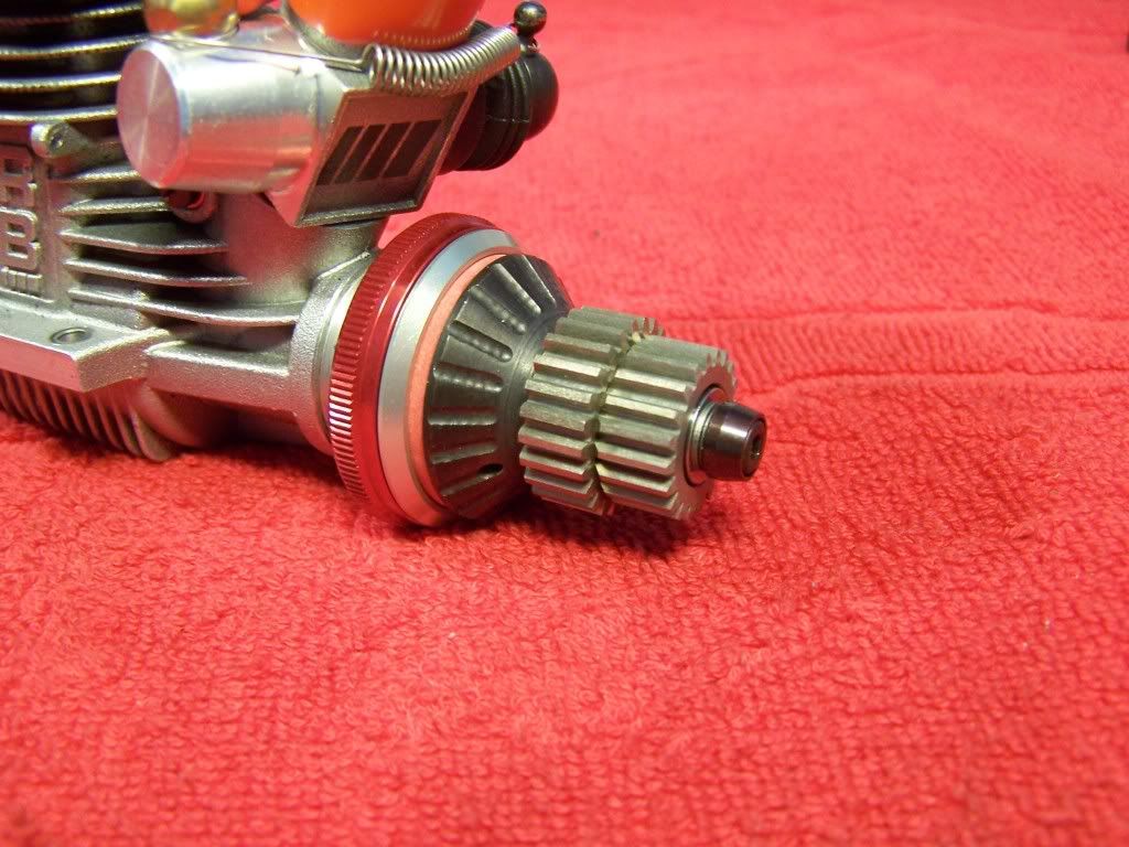
When using an older engine like I did, the ones with the capped screws for the rear cover, you might need to dremel some material off the one piece mount.
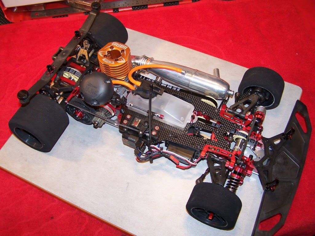
Engine mounted:
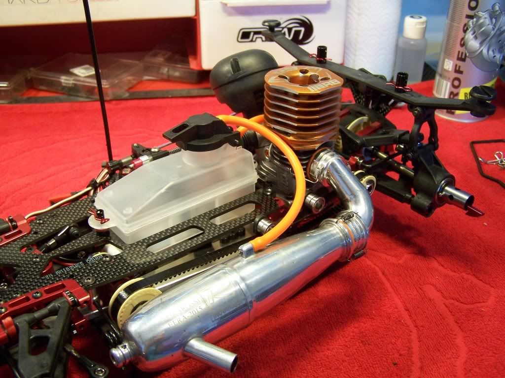
Fully assembled car:
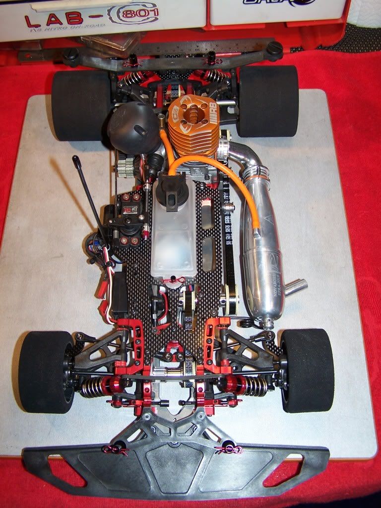
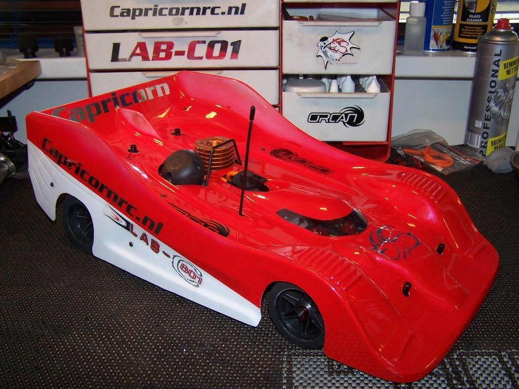
Body on the car:
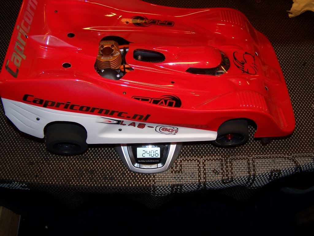
Weight of the car completely stock:
Within a couple of weeks I will post an update about my 2012 car with some option parts fitted to it.

If you have any questions don't hesitate to ask.
