


new to flying
 01-05-2009, 12:53 AM
#1
Hi Guys
Im new to rc planes, my wife got me one for christmas.
Its an Electranet XP2, dont know if anyone knows it
my problem is i crashed it the other day as one does when learning,
when i opened up where the battery sits there was some wires that had come out and made it stop flying.
its right where the frequency chip is inside, there are 3 wires that connect to 3 gold pins each, there are 4 sets of gold pins. they are red, white and black wires and im just not sure where they have to go to work properly
if someone could help me out that would be great, if need be i can take some photos so you guys can see
 01-05-2009, 12:33 PM
#2
I think you meant Electrafun, but no matter. Yeah, a pic would be helpful. The part with the 4 sets of 3 gold pins is the receiver. The receiver in the xp2 is a 4 channel unit. Each of the 4 channels consists of a 3 pin connection, something like this;
*** channel 4
*** channel 3
*** channel 2
*** channel 1
Now, on most, if not all receivers, looking straight on at the pins, with channel 1 at the bottom, as crudely illustrated above, the connector plugs in so that the black wire is on the right. I'm hoping it's the same with your plane. But take a close look at the receiver to see if there are any markings, such as 1 2 3 4 or + - and let us know what you find out.
01-05-2009, 02:04 PM
#3
Cool, thanks heaps for that. I will have a look at it when i get home and let you know.
im guessing the power plug will go into the number that my plane uses right?
ill take a photo aswell but yes that illistration you did was what it looks like
im guessing the power plug will go into the number that my plane uses right?
ill take a photo aswell but yes that illistration you did was what it looks like
01-05-2009, 05:30 PM
#4
Your transmitter has four axes. 2 for each stick. So, moving the;
Right stick left and right is 1 axis.
Right stick up and down is 2.
Left stick up and down is 3.
Left stick left and right is 4.
Now for each of those axes, the transmitter converts your stick movements to radio frequency signals and transmits those signals to the receiver (that's the unit with the gold pins).
*** channel 4
*** channel 3
*** channel 2
*** channel 1
Once the receiver receives the signals, it sends an electrical signal to the appropriate set of pins. Connected to those pins, you would have 2 servos (that make the parts of the tail move) and a speed/throttle controller. Those 3 wires you said came loose are coming from the 2 servos and the speed control, and each connects to the appropriate channel (set of pins) on the receiver. The fourth set of pins is unused.
Now, to clarify, When we're talking about 3 wires, we're talking about 3 ribbons which consist of 3 wires each, with a connector on each, right?
Three of those.
OK so, now we need to find out which axis (or stick movement) corresponds with which channel on your receiver. It should be pretty easy once you get home and get a better look at the receiver and maybe post a pic or two.
01-06-2009, 12:47 AM
#5
I'm not quite sure what you mean by that but
Once the receiver receives the signals, it sends an electrical signal to the appropriate set of pins. Connected to those pins, you would have 2 servos (that make the parts of the tail move) and a speed/throttle controller. Those 3 wires you said came loose are coming from the 2 servos and the speed control, and each connects to the appropriate channel (set of pins) on the receiver. The fourth set of pins is unused.
Now, to clarify, When we're talking about 3 wires, we're talking about 3 ribbons which consist of 3 wires each, with a connector on each, right?
Three of those.
OK so, now we need to find out which axis (or stick movement) corresponds with which channel on your receiver. It should be pretty easy once you get home and get a better look at the receiver and maybe post a pic or two.
however im not sure what is number one and what is number 3.
ill get a photo up here soon i tried to take one but the battery was flat so the image was all blury.
on the receiver there really isnt much to illustrate whats there, how ever on the wires there is one with a P, one with a B and one with an I.
01-06-2009, 03:16 AM
#7
Ok, it seems that no matter what i plug them into it doesnt seem to get going. i put the one that controls the speed into what i believe is channel on so the very bottom one and nothing happened 80% of the time. Every now and then though whether my control is on or not the motor just starts up and doesnt stop unless i disconnect the battery.
Also should my control itself be getting very hot? During all of this the bottom left hand corner of it was getting hotter and hotter, just like where the power control is inside the plane
sorry if some of the terms dont make to much sense, its just what i see them as still learning what they are properly
01-06-2009, 08:02 AM
#8
Don't worry about the terminology for now, we've all been there.
Ok, well I was thinking more of a cautious approach but if you're game to try plugging stuff in and seeing if it works....
The problem is, these planes are manufactured for the various markets and re-named and inconsistently built but, here's what I think yours should look like.
With the wing removed looking down into the canopy from the rear as if you were seated in the plane looking forward; The motor arming button is on the left side of the plane. The speed control is mounted to the left inside the canopy, above and back from the button. The receiver is mounted to the right inside the canopy. The gold pins on the receiver are pointing toward the front of the plane. if all that seems to be right, try the following;
Turn the plane so that the front is pointing toward you. Now the pins on the receiver should be pointing toward you as well. Without the battery connected plug the components in as follows;
*** unused
*** speed control
*** elevator servo
*** rudder servo
On each set of wires, the black wire should be to the right and the white to the left. (I assume no changes have been made to the reversing switches on the transmitter.)
(At this point make sure to either remove the propeller or unplug the motor wires from the speed control or at the very least, be aware that the motor could spin up unexpectedly. )
Now, with that configuration, turn your transmitter on and make sure the throttle stick is all the way down and the throttle trim lever is all the way down as well. Plug a battery in, and without touching the motor arming button, move the control sticks for rudder and elevator. If the tail responds properly, plug the motor wires back in if you've unplugged them, and try arming the motor with the arming button and see if the motor will spin up with throttle stick input.
If all that works, then your set! If not let me know and we can go back to that cautious approach.
01-06-2009, 11:23 AM
#9
When you say your control is getting hot, do you mean the speed control, which is inside the plane? Or the transmitter, which of course is the handheld gizmo with the sticks.
The speed control in these planes are not the greatest and it will get quite warm when in use. But shouldn't ever get into the ~200�F (93.3�C) range . The transmitter shouldn't be getting hot at all.
The speed control in these planes are not the greatest and it will get quite warm when in use. But shouldn't ever get into the ~200�F (93.3�C) range
. The transmitter shouldn't be getting hot at all.
01-07-2009, 12:53 AM
#10
ok so i have tried that configuration and following what you have said but nothing still seems to happen, even once its all plugged in i move the toggles on the transmitter nothing happens.
whats the more cautious approach?
and its the bottom left hand corner of the transmitter near the frequency crystal that is getting quite warm once the power on the remote is turned on.
i hope at least something of this is making sense cos i understand everything your saying but i dont get why its not working.
and thanks for being such a help aswell
01-07-2009, 07:25 PM
#11
(I've done a bit of editing here, so you might need to re-read the post. Nothing major, I was just tired the first time around)
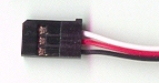
Alright then, let's backtrack just a bit. Here's a couple pics of my setup;

That's exactly how it sits in the plane. The side you can't see, attaches to the inside right wall of the canopy. With the pins pointing toward the front and the crystal pointing to the rear of the plane.
Notice the crystal is up high in the receiver. If yours is down low, it might be upside-down compared to the way mine is mounted. That's the question. Is yours oriented the same as mine? Also notice all the black wires on my plugs are to the right as you're looking at the pins. If your receiver is mounted reverse of mine, everything else will be backward too. Black wires on the other side, bottom channel not being used, etc. The other difference is, over here we use mode 2 transmitters and you guys use mode 1 (I think), so your speed control's plug and elevator servo's plug may be switched around from the way mine are.
So, the top set of pins is unused and the next set down is my speed control plug. The other 2 are the servos. My servos just happen to use yellow wires instead of white. Wire colors vary with manufacturer but we'll just stick with black, red, and white for this discussion. Your receiver and servos run on about 4.5-6.0 volts supplied by the speed control, but I'm going to use 5 volts in this example.
The speed control wires are;
Black= neg 5v from the speed control to power the receiver and the servos.
Red= pos 5v from the speed control to power the receiver and the servos.
White= the signal from the receiver that tells the speed control what the transmitter want's it to do.
The servo wires are;
Black= neg 5v from the receiver to power the servo.
Red= pos 5v from the receiver to power the servo.
White= the signal from the receiver that tells the servo what the transmitter wants it to do.
Keep in mind the battery powers the speed control, and the black and red wires from the speed control power the receiver. Then, the servos draw power from the receiver through the black and red wires. The white wires are for signal only. So, in the receiver, all 4 of the terminals for pos 5v are linked together, and all 4 of the terminals for neg 5v are linked together. The terminals for the white (signal) wires are relatively independent of each other. Get a multimeter if you don't already have one, and check for continuity (ohms) between those rows of "black" pins Which will show a direct link to each other and the "red" pins which will show a direct link to each other. The white pins will show resistance or no continuity between them. Once you find the row of pins that shows resistance or no continuity, you know that's where the white wires go.
More on the multimeter. You don't need an expensive one or anything, just one that'll do low dc voltage and ohms. They run about 10 bucks here (US), I dunno bout there.
So, for your receiver, if we plug 5v power to the positive and negative terminals of any of the 4 channels, the pos and neg terminals of the other 3 channels should have 5v power as well.
Now for the cautious approach. You're going to need your volt meter, or at least some way of testing for voltage. The first thing we need to do is get power to your receiver so we can see if your receiver and transmitter are working.
Ok first, make sure your batteries for the transmitter and plane are charged. Then take the crystal out of your transmitter and check to see if the pins are clean, plug it back in and wiggle it gently to make sure it's well seated. Hopefully that will take care of the heat problem there.
Next, with the speed control disconnected from the motor and receiver, connect the battery to the speed control and place the test probes from your volt meter on the black and red wires at the speed control's 3 wire receiver plug. You should have about 5v there, if you don't there's a prob with the speed control.
Now to power up the receiver. Take your 3 wire plug on the speed control and temporarily remove the white wire from the plug. Use an exacto knife or something similar, and gently pry up the plastic retainer, and slide the metal connector out of the plug. Pay attention to how it came out, so you can replace it later. Fold the wire back, out of the way.

Now connect your rudder servo to channel 1, 2, or 3 of the receiver with the white wire on the correct pin. Turn on your transmitter. With the battery connected to your speed control, connect the 3 wire plug (with white wire removed) from your speed control into channel 4 of your receiver. Move the sticks on the transmitter in circles and see if the servo moves. If it doesn't, but every thing else up to now has worked, there's a problem with the receiver or transmitter. If it does, you can change plug locations of that servo, till it responds to the right stick moved left and right. Then plug the elevator servo into which ever channel reacts to left stick up and down.
So far if the tail servos are working, all you have to do is unplug battery, unplug the 3 wire connector for the speed control and replace the white wire. Plug the motor into the speed control or use your volt meter in place of the motor. Plug the speed control into an open channel on the receiver and plug the battery in. Make sure the throttle stick and trim lever are down, transmitter is still on and plug in the battery. Arm the motor and see if it responds correctly to stick input. If it doesn't try the other channel. If it does, go fly the bugger.
Sorry about the novel I've written here but I'm just trying to cover all the bases.
Alright then, let's backtrack just a bit. Here's a couple pics of my setup;
That's exactly how it sits in the plane. The side you can't see, attaches to the inside right wall of the canopy. With the pins pointing toward the front and the crystal pointing to the rear of the plane.
Notice the crystal is up high in the receiver. If yours is down low, it might be upside-down compared to the way mine is mounted. That's the question. Is yours oriented the same as mine? Also notice all the black wires on my plugs are to the right as you're looking at the pins. If your receiver is mounted reverse of mine, everything else will be backward too. Black wires on the other side, bottom channel not being used, etc. The other difference is, over here we use mode 2 transmitters and you guys use mode 1 (I think), so your speed control's plug and elevator servo's plug may be switched around from the way mine are.
So, the top set of pins is unused and the next set down is my speed control plug. The other 2 are the servos. My servos just happen to use yellow wires instead of white. Wire colors vary with manufacturer but we'll just stick with black, red, and white for this discussion. Your receiver and servos run on about 4.5-6.0 volts supplied by the speed control, but I'm going to use 5 volts in this example.
The speed control wires are;
Black= neg 5v from the speed control to power the receiver and the servos.
Red= pos 5v from the speed control to power the receiver and the servos.
White= the signal from the receiver that tells the speed control what the transmitter want's it to do.
The servo wires are;
Black= neg 5v from the receiver to power the servo.
Red= pos 5v from the receiver to power the servo.
White= the signal from the receiver that tells the servo what the transmitter wants it to do.
Keep in mind the battery powers the speed control, and the black and red wires from the speed control power the receiver. Then, the servos draw power from the receiver through the black and red wires. The white wires are for signal only. So, in the receiver, all 4 of the terminals for pos 5v are linked together, and all 4 of the terminals for neg 5v are linked together. The terminals for the white (signal) wires are relatively independent of each other. Get a multimeter if you don't already have one, and check for continuity (ohms) between those rows of "black" pins Which will show a direct link to each other and the "red" pins which will show a direct link to each other. The white pins will show resistance or no continuity between them. Once you find the row of pins that shows resistance or no continuity, you know that's where the white wires go.
More on the multimeter. You don't need an expensive one or anything, just one that'll do low dc voltage and ohms. They run about 10 bucks here (US), I dunno bout there.
So, for your receiver, if we plug 5v power to the positive and negative terminals of any of the 4 channels, the pos and neg terminals of the other 3 channels should have 5v power as well.
Now for the cautious approach. You're going to need your volt meter, or at least some way of testing for voltage. The first thing we need to do is get power to your receiver so we can see if your receiver and transmitter are working.
Ok first, make sure your batteries for the transmitter and plane are charged. Then take the crystal out of your transmitter and check to see if the pins are clean, plug it back in and wiggle it gently to make sure it's well seated. Hopefully that will take care of the heat problem there.
Next, with the speed control disconnected from the motor and receiver, connect the battery to the speed control and place the test probes from your volt meter on the black and red wires at the speed control's 3 wire receiver plug. You should have about 5v there, if you don't there's a prob with the speed control.
Now to power up the receiver. Take your 3 wire plug on the speed control and temporarily remove the white wire from the plug. Use an exacto knife or something similar, and gently pry up the plastic retainer, and slide the metal connector out of the plug. Pay attention to how it came out, so you can replace it later. Fold the wire back, out of the way.
Now connect your rudder servo to channel 1, 2, or 3 of the receiver with the white wire on the correct pin. Turn on your transmitter. With the battery connected to your speed control, connect the 3 wire plug (with white wire removed) from your speed control into channel 4 of your receiver. Move the sticks on the transmitter in circles and see if the servo moves. If it doesn't, but every thing else up to now has worked, there's a problem with the receiver or transmitter. If it does, you can change plug locations of that servo, till it responds to the right stick moved left and right. Then plug the elevator servo into which ever channel reacts to left stick up and down.
So far if the tail servos are working, all you have to do is unplug battery, unplug the 3 wire connector for the speed control and replace the white wire. Plug the motor into the speed control or use your volt meter in place of the motor. Plug the speed control into an open channel on the receiver and plug the battery in. Make sure the throttle stick and trim lever are down, transmitter is still on and plug in the battery. Arm the motor and see if it responds correctly to stick input. If it doesn't try the other channel. If it does, go fly the bugger.
Sorry about the novel I've written here but I'm just trying to cover all the bases.
Last edited by helibrian; 01-09-2009 at 06:54 AM.
01-08-2009, 10:25 PM
#12
Ok thanks for that, the pictures are good thats exactly what mine looks like aswell.
ill let you know once i give it a shot. I just gotta get the voltmeter cos i do have a sneaky suspicion that there isnt any power getting through to what it has to.
BTW thanks heaps
ill let you know
ill let you know once i give it a shot. I just gotta get the voltmeter cos i do have a sneaky suspicion that there isnt any power getting through to what it has to.
BTW thanks heaps
ill let you know
01-30-2009, 09:05 PM
#13
Just thought i would let you know ive just about got it working, i went and got a new receiver and its seems to be functioning ok at the moment, the power cable came loose cos i had it outside in the shed and its been about 40degrees here latley so the clue that held it together just came off. im goin to put the wires back onto where it was and its ok so far.
just thought i would let you know and thanks for all the help
just thought i would let you know and thanks for all the help
02-02-2009, 03:37 PM
#14
Just thought i would let you know ive just about got it working, i went and got a new receiver and its seems to be functioning ok at the moment, the power cable came loose cos i had it outside in the shed and its been about 40degrees here latley so the clue that held it together just came off. im goin to put the wires back onto where it was and its ok so far.
just thought i would let you know and thanks for all the help
just thought i would let you know and thanks for all the help
Currently Active Users Viewing This Thread: 1 (0 members and 1 guests)
