


 16Likes
The Homebuilt Dynamometer (Dyno)Thread!!!


 11-20-2015, 10:53 AM
#47
Yes, but as Jebarus stated it would only be approximate. All of our banter is based on a very simple motor model. That model implies that if you advance the timing, and the Kv increases, then the Kt decreases by the same amount, leaving the peak power output constant. We know that this is not true, and that's why we want to make a dyno!

I either still don't understand where the variations in efficiency (which cause the change in peak power, right?) come from, or I did back we exchanged when I was writing my articles, and now I forgot.

In any case, I've got a train journey this weekend, I'll be playing around with gnuplot, see what this gives me. I tested the free-running RPM of my Reedy Sonic M3 10.5T motor for every 10�, from 0� to 90� yesterday (went from 12,500 to 69,000!).
I think I also discovered that my Reedy Blackbox 410R ESC might have a built-in limit of 60� to the dynamic timing it will apply, and I believe (but need to confirm) that other ESCs might not be so "shy"... Some people run their motor with 10-20� of static timing, but use 70-80� of total dynamic timing (hitting that maximum only briefly, on the straight, of course!). My attempts at similar setups tended to leave me behind on the straight, being good everywhere else, that limit might explain it.
I'm trying 30� of static timing tonight, and I'll ramp up the dynamic timing progressively to see how that goes, but now I'm wondering if this isn't too much timing at low RPMs... Hence my attempt to at least get a rough idea of the actual torque curves of my motor, to see how wrong I am.
11-20-2015, 11:40 AM
#48
But you are already familiar with this, as shown in your excellent articles on motor timing!:
http://www.rctech.net/forum/radio-el...y-boosted.html
11-20-2015, 04:46 PM
#49
But you are already familiar with this, as shown in your excellent articles on motor timing!:
http://www.rctech.net/forum/radio-el...y-boosted.html
http://www.rctech.net/forum/radio-el...y-boosted.html

No, what I mainly meant when I said that I didn't understand is the reasons why there are those variations in efficiency when changing the timing, why the peak power isn't constant when changing the timing (just moving at what RPM it gets delivered), that sort of stuff...
12-16-2015, 05:00 AM
#50
It's time for a status report!
The SimpleDyno software has been giving some curious results. The shape of the power curve and the location of the power peak are quite a bit different than expected, and multiplying the reported torque and speed does not equal the reported power; I can scale the result so it is correct at one speed, but using the same scale at a different speed results in a power discrepancy. I have posted questions on the SimpleDyno forum, but have yet to receive any responses.
As a result, I did some further simulation work, which has revealed that my original guess at the number of revolutions for getting (what I consider to be) accurate readings was very conservative. I used a spreadsheet to generate an exponential curve for the velocity versus time during spool-up (which assumes zero losses due to friction and drag), and then calculated the time between each integer revolution of the motor. The time between each integer revolution of the motor simulates the data that will come from the actual motor and flywheel. I then used a simple linear interpolation for calculating the values of velocity, acceleration, and mechanical power output from the motor.
It turns out that a flywheel large enough for the motor to spin up in just ten revolutions will give calculated power results repeatable to better than 0.06%. In other words, the power calculated at the ninth or eleventh revolution (since we don't necessarily know at what angle the motor starts at) is within 0.06% of the power calculated at the tenth revolution.
The simulation also showed that the calculations require a very precise measurement of time between revolutions: a 1us change in the measured period corresponds to about 0.1% error in the power calculation. This does not bode well for SimpleDyno, because it uses the PC's microphone input to gather data, and the maximum sample rate is 44kHz (about 23us period). So it looks like I may need to create a little microprocessor gizmo to time the motor revolutions and send the results to the PC, where they can be processed in any manner desired.
Last edited by howardcano; 12-16-2015 at 05:10 AM.
12-16-2015, 08:28 AM
#51
I went back and read what I just wrote... The requirement for such precise measurement of time between motor revolutions got me very concerned about using gears, since they necessarily add some play/backlash in the system, and this could affect the time measurements. Direct coupling of the motor to flywheel would eliminate this concern, and maybe reduce the number of parts necessary to make the dyno, but also adds the interesting design problem of supporting the motor shaft so it won't whip about (or break!), while maintaining alignment and contributing little friction.
Last edited by howardcano; 12-17-2015 at 04:00 AM.
12-20-2015, 08:47 AM
#52
For a direct connection that can withstand some slight misalignment, what about speedometer cable or power seat cable with aluminum collars with set screws at both ends for attaching to the motor and cable? Speedometer cable may be harder to come by than the power seat part since it's been quite a while actually seeing one of those on a car.
12-21-2015, 05:28 AM
#53
For a direct connection that can withstand some slight misalignment, what about speedometer cable or power seat cable with aluminum collars with set screws at both ends for attaching to the motor and cable? Speedometer cable may be harder to come by than the power seat part since it's been quite a while actually seeing one of those on a car.
I was thinking something similar to a third-bearing clutch support on a kart, with a solid connection between motor and flywheel, but with restriction on radial movement and wobble.
But first we will need to see the if the data from many runs with the gear reduction shows undue scatter, or if all of my worries are unfounded!
12-21-2015, 09:18 AM
#54
I still use the slave motor set up, I prefer a brushed motor as the s motor witj a voltmeter to read RPM. The most important part is the coupler (Make one if you can find one, do not use fuel tubing . It needs to be metal with grub screws) It then will be much more accurate
Tom
Tom
12-21-2015, 09:49 PM
#55
That would certainly take care of misalignment, but I fear that the time data would be severely skewed due to twisting of the cable. 1us of time doesn't equate to much angle at these speeds; it's about 0.05 degrees at 8000 RPM. I'm guessing that the cable would probably twist at least an order of magnitude more than that.
Keeping my fingers crossed. As before, you have me intrigued again with one of your projects. I really need to work on my electronics knowledge.
12-22-2015, 02:58 PM
#56
I'm liking this idea a lot! If the flywheel shaft and motor shaft are nearly collinear, then the losses and rotational error from just a simple dogbone would be negligible. And it eliminates the need for the very critical alignment of the third-bearing arrangement. It's time to start digging through the drivetrain parts!
12-22-2015, 10:53 PM
#57
Something like this?
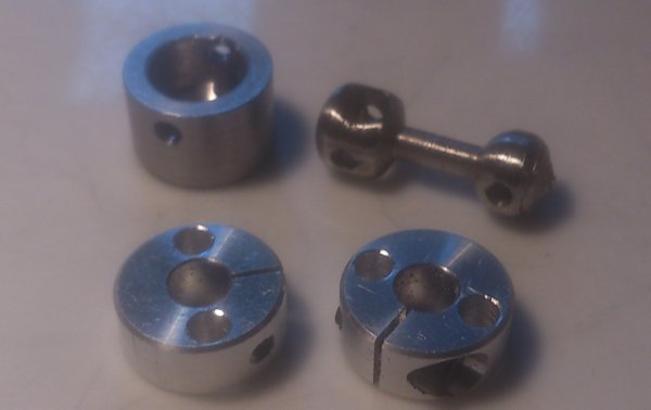
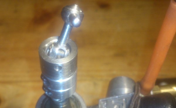
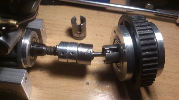
I am busy with something else and made a short CVD shaft with 2 (standard) clamps to connect an engine to an electrical drive w/o a precise alignment.
I am busy with something else and made a short CVD shaft with 2 (standard) clamps to connect an engine to an electrical drive w/o a precise alignment.
12-25-2015, 06:56 PM
#59
I have lots of data from the Eagle Racing MD2 dyno if that helps anyone wanting to build a dyno. What's needed to make the MD2 dyno better is higher sample rate (it's only 50hz) and more accurate current/voltage measurement. If the sample rate was increased to say 500 hz with a larger flywheel you would really have something.
I really like the idea of a geared dyno. At least it keeps the flywheel RPM down and if you are using it to do your own comparisons errors due to gear friction would be irrelevant since you would use the same value for all tests. Apple to apple. I would expect the loss to be less than 5% for a single gear mesh but that's just a guess. A 1:1 drive with a much larger flywheel would also be good but the RPM for a low turn motor with boost would be terrifying. The MD2 dyno shuts off at 30000 RPM and that's a good thing IMO.
One thing to note is the torque output of a brushless motor is not linear particularly at higher timing settings. I have spent lots of time researching modeling DC Motors and you can get good agreement with a simple model for brushed motors. With brushless motors at higher timing settings all this goes out the window. If you look at the Silver Can graph below you can see the torque output is reasonably linear. Then look at the Orion Motor and you can see as the motor timing is increased the Torque output becomes much more non-linear.
12-25-2015, 08:05 PM
#60
Thanks for the excellent input and data, Bob!
I intend to count the time between successive revolutions to a resolution of at least 1us, which would be equivalent to sampling at 1MHz; anything less than that will not give me the accuracy I desire.
For the moment, I won't be doing any current measurement, so I won't be able to determine efficiency. But my main interest is determining power output vs timing.
I agree that gearing can keep the flywheel to sane speeds, and also reduce aerodynamic power losses (which increase as the cube of the speed). But I still need to establish that the data won't be compromised by the gear lash.
On another note, I have acquired a nice switching power supply (Meanwell RSP3000) which is adjustable over the full range of voltages equivalent to 1s through 3s LiPo. This should reduce voltage droop to negligible values during a run. But it does require 220V, so I need to unplug the clothes dryer if I want to run the dyno!