


 16Likes
The Homebuilt Dynamometer (Dyno)Thread!!!
 11-13-2015, 07:27 PM
#16
Eagletree used to have components. I havent looked to see if they are even in business anymore.
 11-14-2015, 03:30 AM
#17

I see you're working with nitro cars, but could this be modified to gather some other information, putting probes on the motor power and sensor leads, and measure how much timing advance the ESC is applying?
A bit off-topic, but that whole telemetry/data recording business also seems very interesting, albeit in a palliative way. I could do drag runs, with various timing settings, and at least get my boost settings in the ballpark...
A bit off-topic, but that whole telemetry/data recording business also seems very interesting, albeit in a palliative way. I could do drag runs, with various timing settings, and at least get my boost settings in the ballpark...
Off-track testing and tuning can be usefull but still you have to translate it to the setup of a car. Looking at a lot of toplevel drivers I do see they are not working with test benches but getting as much tracktime as possible to setup the whole car and also important: to get the track in the fingers.
And then a real time (recorded) telemetry will show directly if there are improvements or not. But finally the laptime is the most important and there are enough situations where the maximum performance of the motor does not count.
 11-14-2015, 03:38 AM
#18
11-14-2015, 03:52 AM
#19
This is an old data aquisition box with 8 analog, 8 digital and 1 timing input. You can connect all kind of sensors as long you make the range of 0-2.5v or digital max 5v on/of switching signal. The software is modulair so you can set it up with even re-calculations on the range.
Off-track testing and tuning can be usefull but still you have to translate it to the setup of a car. Looking at a lot of toplevel drivers I do see they are not working with test benches but getting as much tracktime as possible to setup the whole car and also important: to get the track in the fingers.
But in boosted (dynamic timing) racing, getting the most power out of a motor is a completely straightforward process, if you have the torque/timing curve data (which should be fairly simple with a flywheel dyno). It's not even a matter of taste or set-up tuning, once it's set up right, you'll never need to tweak it (unlike timing in blinky racing), but without the data, it's some very difficult guesswork (as you're also trying to work out the right gearing, so a lack of punch or top speed could be either, with almost nothing to tell you).
For blinky racing, it's a lot simpler, and I'd say that other than some simple "how much timing is too much" (that you could do on the track without too much difficulty), there isn't much that a dyno can tell you that you couldn't find out at the track, for a given motor (a big budget racer could use a dyno to pick out the best motor out of a bunch, but I'm not interested by that).
11-14-2015, 04:47 AM
#20
This system does 2 whole string (17 inputs) of samples per second. One of the reasons that is is that slow is a reliable transmitting data on larger distances with low power.
Data aquisition wit a 1khz sampling rate is possible, but does require more advanced systems.
Data aquisition wit a 1khz sampling rate is possible, but does require more advanced systems.
11-14-2015, 03:07 PM
#21
I guess that timing is implemented using interrupts in the ESC microcontroller. Instead of fast analog sampling, the microcontroller monitors a digital pin. There is a comparator in the microcontroller, and as soon as the comparator is activated (either by a up, down, or up or down signal), a piece of code is executed.
11-14-2015, 03:18 PM
#22
I built this thing with my collegue about 10 months ago: i.imgur.com/3vYNipR.png
It is too bad we did not take a picture...We were attempting to build a direct drive micro helicopter. The whole helicopter was mounted on bearings. There is a load cell at the back to measure torque. The motor was loaded with the prop. We could change dynamically the motor loading by moving the swash plate, and we were measuring the thrust.
The whole thing could run completely automated tests, and it had a nice matlab gui. It was using arduinos for data acquisition, op-amps for load cells, load cells savaged from kitchen scales, and a current sensor.
Here is a picture of the micro helicopter prototype:
i.imgur.com/acuyEaf.jpg
11-14-2015, 04:01 PM
#23
A 2000kv motor will spin at about 230Hz with no load. 1k might be a bit low, but it might just do it. The wire that goes from the ESC to the motor usually has 6 wires. What kind of encoding is used?
I guess that timing is implemented using interrupts in the ESC microcontroller. Instead of fast analog sampling, the microcontroller monitors a digital pin. There is a comparator in the microcontroller, and as soon as the comparator is activated (either by a up, down, or up or down signal), a piece of code is executed.
I guess that timing is implemented using interrupts in the ESC microcontroller. Instead of fast analog sampling, the microcontroller monitors a digital pin. There is a comparator in the microcontroller, and as soon as the comparator is activated (either by a up, down, or up or down signal), a piece of code is executed.
Here's a diagram of the sensor outputs and motor drive:

A comparator isn't needed, since the Hall sensor outputs have digital levels.
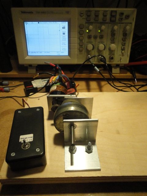
I have tapped into one of the sensor signals with a 100K-ish series resistor to reduce loading and attenuate the signal going into the microphone input of my laptop, which is what the SimpleDyno freeware program uses for speed sensing. The mic input can be sampled at 44.1 kHz, so the resolution is pretty good.
11-14-2015, 05:22 PM
#24
11-14-2015, 05:28 PM
#25
I was thinking "at least double it, for Nyquist". I know just enough to be dangerous... ;-)
11-15-2015, 02:44 AM
#26
Actually, you are correct if the RPM is determined by counting the frequency over a gate time. One second gating with a 300 Hz input gives 300 cycles, which is 1/3% resolution. But that requires that the motor speed remain stable over the gate time. That isn't the case for a flywheel dynamometer, but could be for an absorption (brake) dynamometer. So my answer was biased by my preference for a flywheel dyno.
11-15-2015, 04:14 AM
#27
Actually, you are correct if the RPM is determined by counting the frequency over a gate time. One second gating with a 300 Hz input gives 300 cycles, which is 1/3% resolution. But that requires that the motor speed remain stable over the gate time. That isn't the case for a flywheel dynamometer, but could be for an absorption (brake) dynamometer. So my answer was biased by my preference for a flywheel dyno.
11-15-2015, 03:47 PM
#28
It must use a six position JST ZH connector model number ZHR-6 or equivalent
connector with 6 JST part number SZH-002T-PO.5 26-28 awg contacts or equivalent.
Wire sequence must be as follows:
Pin #1- ground potential
Pin #2- phase C
Pin #3- phase B
Pin #4- phase A
Pin #5- temp control, 10 k Thermistor referenced to ground potential
Pin #6- + 5.0 volts =/- 10%
connector with 6 JST part number SZH-002T-PO.5 26-28 awg contacts or equivalent.
Wire sequence must be as follows:
Pin #1- ground potential
Pin #2- phase C
Pin #3- phase B
Pin #4- phase A
Pin #5- temp control, 10 k Thermistor referenced to ground potential
Pin #6- + 5.0 volts =/- 10%
The comparator I was talking about is just an implementation detail. It is how the ESCs are doing it, and it is very accurate. Most microcontroller will have pins that can execute code when triggered. The comparator is actually inside the microcontroller. Those pins are monitored internally in the MHz range. The trick is that you tell the microcontroller, each time this pin is triggered, save the time in a variable. The time is very accurate, so you can subtract the old time to the new time, and obtain the phase length in microseconds. The phase length is inversely proportional to the RPM.
11-16-2015, 03:55 AM
#29
By the way, the thermistor is unfortunately not required for a motor to be approved by ROAR.
Most microcontroller will have pins that can execute code when triggered. The comparator is actually inside the microcontroller. Those pins are monitored internally in the MHz range. The trick is that you tell the microcontroller, each time this pin is triggered, save the time in a variable. The time is very accurate, so you can subtract the old time to the new time, and obtain the phase length in microseconds. The phase length is inversely proportional to the RPM.
11-18-2015, 06:01 AM
#30
I just took some rough data from the flywheel shown in one of my posts in the RC Benchmark thread. It weighs 458g, and has an OD of about 2.25" (the weight is not evenly distributed across the disk). I ran it using a 21.5 motor on 1s LiPo with 23T/44T 32 pitch gears (a 1.91:1 reduction of speed from motor to flywheel).
My initial target was to have sufficient effective MOI to get about a 1% change in velocity between readings (one reading per revolution) at the motor's power peak (which occurs at about 50% of the free-running speed). Modeling showed that requires about 40 total motor revolutions with the required MOI.
The data showed that the motor reached 50% speed after about 4 revolutions, or a factor of 10 less than desired. If I change the gear ratio to 1:1, that gains me a factor of about 3.66 (1.91^2). That means the flywheel MOI must increase by a factor of 2.73 to get me where I want to be. Time to try a larger flywheel!
Last edited by howardcano; 11-18-2015 at 02:01 PM. Reason: Changed "revolutions" to "motor revolutions".