


 7Likes
Lap Timing Decoder
 12-22-2012, 02:14 PM
#1

Here's some news on the decoder that I mentioned in my Transponder Design thread.
When I use the term "decoder" in this thread, I mean the system which detects the transponders as they pass the start/finish line. It uses the receiving loop for its input, and sends messages to the lap counting computer. We can break the decoder down into subsystems, including some sort of amplifier, probably with Automatic Gain Control (AGC), to increase the signals induced in the receiving loop by the transponders to usable levels; a detector (or demodulator, the fancy term) to extract the data from the signals; and some sort of microprocessor to translate the data into messages for the lap counting computer.
My first try at a phase detector/demodulator for the decoder is running. It turns out that the phase-locked-loop (PLL) that I mentioned in my Transponder Design thread was unnecessary. Only some simple logic gates are required. This is nice, as PLL circuitry is analog, and logic gates are digital. Digital stuff tends to be easier to reproduce and operates with fewer worries than analog stuff (and this comes from an analog guy-- me!).
The transponders send their data via phase modulation of the 5 MHz carrier, at a data rate of one bit per four carrier cycles. Detecting phase inversions in the carrier is simply a matter of sampling the instantaneous level (using digital levels, either high or low), storing it for one (or up to four, in this case) full cycles, and then comparing a new sample level with the stored level. If the new level is opposite the stored level, then a phase inversion has occurred, and this should result in an output pulse from the detector. This is easily accomplished using a 5 MHz clock, some D flip flops, and an exclusive-or gate.
One complication arises from the fact that the transponder carrier and the clock used in the detector are not at the exact same frequency, and even if they were, their phase relationship is unknown. We'll call the difference in frequencies the "beat frequency". This can lead to the generation of spurious output pulses from the detector during those times when the detector samples the carrier waveform when the waveform level is ambiguous, i.e, near its zero-crossings. One way to eliminate these spurious pulses is by using two detectors running in parallel, with their sample clocks offset by 90 degrees (quadrature operation), and then doing a logical AND of their outputs. When one detector samples the carrier waveform near its zero-crossing and generates a spurious output pulse, the other detector is sampling a different point of the carrier waveform that is far from zero, and does not generate a spurious pulse. When a phase inversion occurs in the carrier, then both detectors generate pulses, and this condition is the one that is valid.
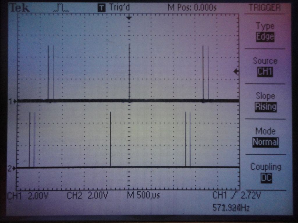
Here's a scope shot of the outputs of the two detectors, using an unmodulated carrier input. As described above, each generates spurious pulses, but the pulses never coincide. (In fact, the pulses tend to occur twice as often as the beat frequency since there are two zero crossings-- positive-going and negative-going-- and about 90 degrees apart, due to the quadrature arrangement of the sample clocks.)
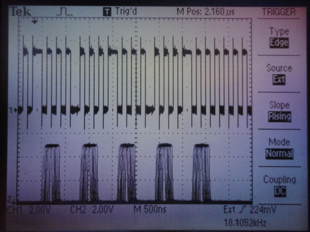
This scope shot shows the final result. The upper trace is the modulated carrier, and the lower trace shows the logical AND of the two detector outputs. (The carrier is actually the digital drive waveform for the transponder tank-- it's best to start simple!) You can see there is one pulse per carrier phase inversion, with the pulse delayed by the latency inherent in the detector design. The bottom trace is "fuzzy" because the carrier and detector sample clocks are different, and the scope is triggered by the carrier. This makes the bottom trace jitter back and forth a little.
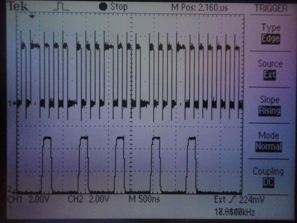
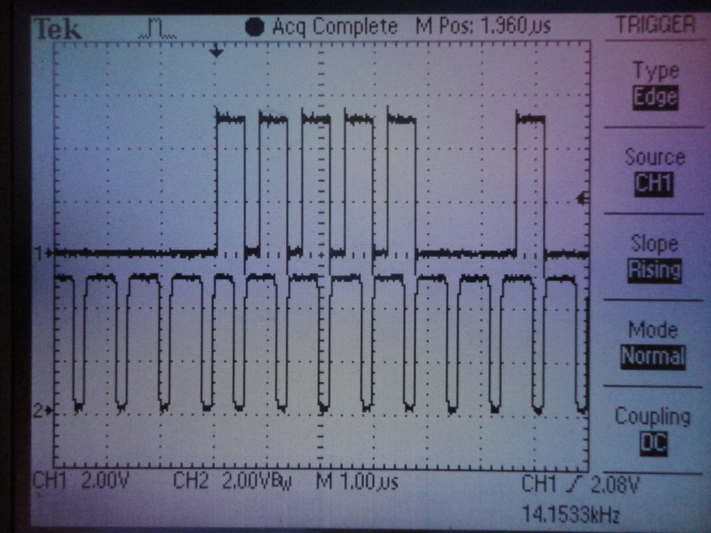
Here's a single sweep of the same thing, which eliminates the "shake" and makes things more obvious:
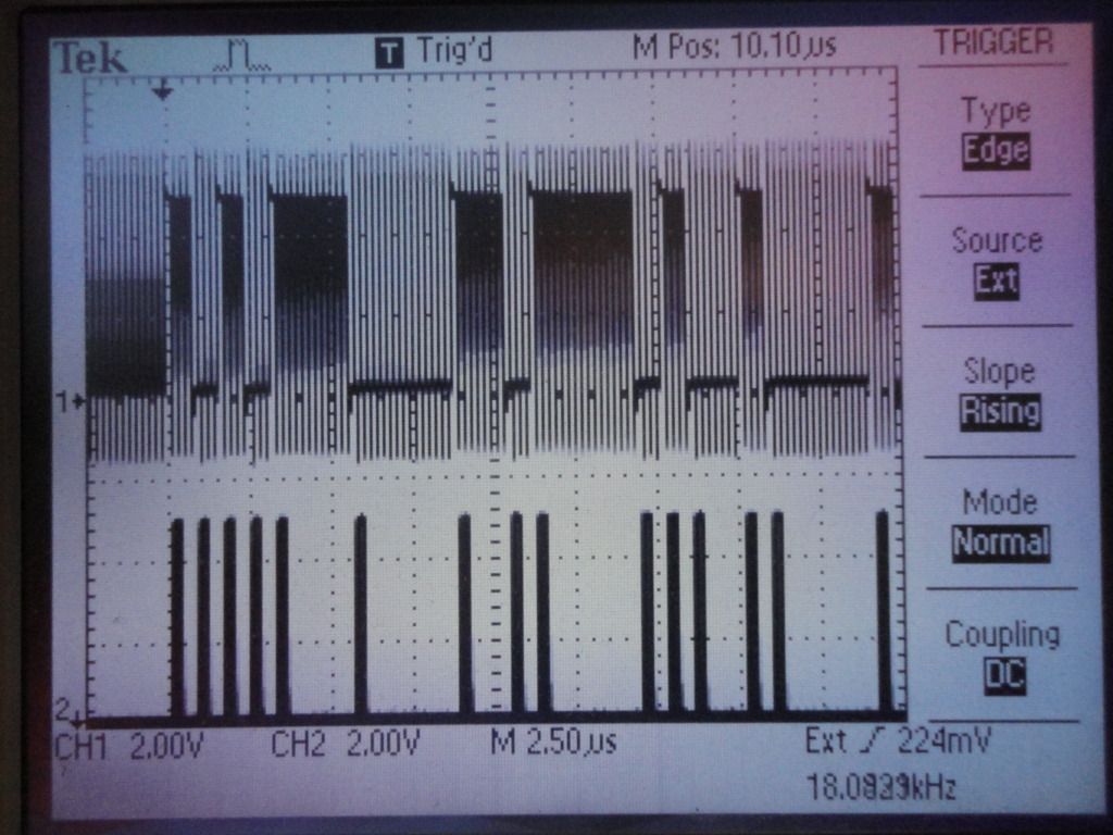
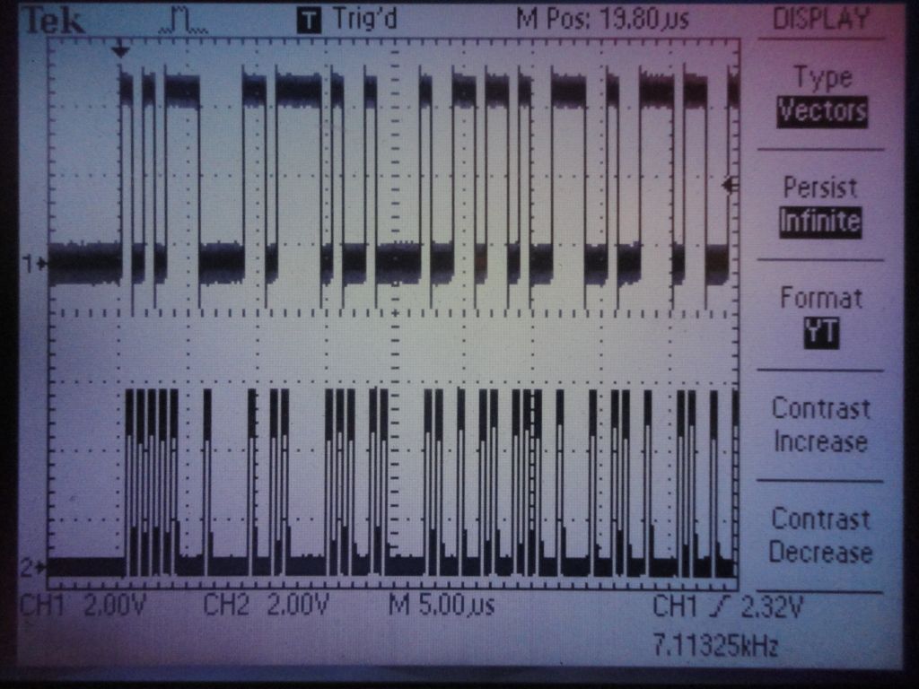
Here is the detector output for a larger number of bits:
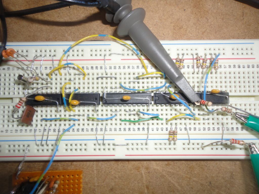
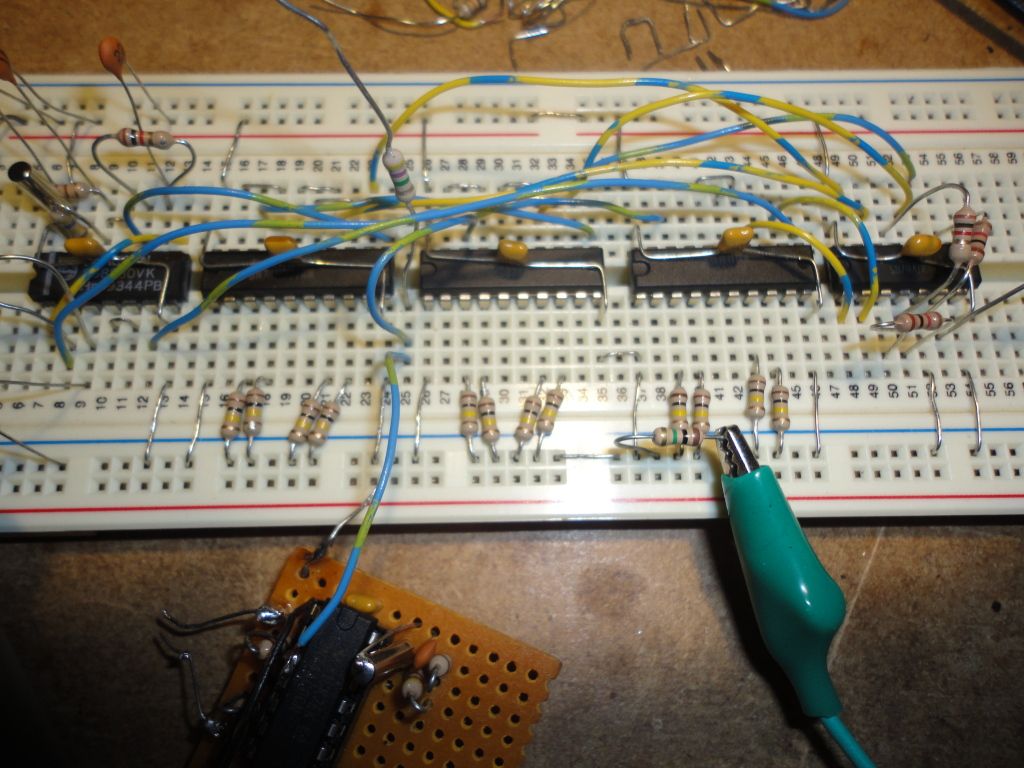
And finally, the ugly solderless breadboard:
When I use the term "decoder" in this thread, I mean the system which detects the transponders as they pass the start/finish line. It uses the receiving loop for its input, and sends messages to the lap counting computer. We can break the decoder down into subsystems, including some sort of amplifier, probably with Automatic Gain Control (AGC), to increase the signals induced in the receiving loop by the transponders to usable levels; a detector (or demodulator, the fancy term) to extract the data from the signals; and some sort of microprocessor to translate the data into messages for the lap counting computer.
My first try at a phase detector/demodulator for the decoder is running. It turns out that the phase-locked-loop (PLL) that I mentioned in my Transponder Design thread was unnecessary. Only some simple logic gates are required. This is nice, as PLL circuitry is analog, and logic gates are digital. Digital stuff tends to be easier to reproduce and operates with fewer worries than analog stuff (and this comes from an analog guy-- me!).
The transponders send their data via phase modulation of the 5 MHz carrier, at a data rate of one bit per four carrier cycles. Detecting phase inversions in the carrier is simply a matter of sampling the instantaneous level (using digital levels, either high or low), storing it for one (or up to four, in this case) full cycles, and then comparing a new sample level with the stored level. If the new level is opposite the stored level, then a phase inversion has occurred, and this should result in an output pulse from the detector. This is easily accomplished using a 5 MHz clock, some D flip flops, and an exclusive-or gate.
One complication arises from the fact that the transponder carrier and the clock used in the detector are not at the exact same frequency, and even if they were, their phase relationship is unknown. We'll call the difference in frequencies the "beat frequency". This can lead to the generation of spurious output pulses from the detector during those times when the detector samples the carrier waveform when the waveform level is ambiguous, i.e, near its zero-crossings. One way to eliminate these spurious pulses is by using two detectors running in parallel, with their sample clocks offset by 90 degrees (quadrature operation), and then doing a logical AND of their outputs. When one detector samples the carrier waveform near its zero-crossing and generates a spurious output pulse, the other detector is sampling a different point of the carrier waveform that is far from zero, and does not generate a spurious pulse. When a phase inversion occurs in the carrier, then both detectors generate pulses, and this condition is the one that is valid.
Here's a scope shot of the outputs of the two detectors, using an unmodulated carrier input. As described above, each generates spurious pulses, but the pulses never coincide. (In fact, the pulses tend to occur twice as often as the beat frequency since there are two zero crossings-- positive-going and negative-going-- and about 90 degrees apart, due to the quadrature arrangement of the sample clocks.)
This scope shot shows the final result. The upper trace is the modulated carrier, and the lower trace shows the logical AND of the two detector outputs. (The carrier is actually the digital drive waveform for the transponder tank-- it's best to start simple!) You can see there is one pulse per carrier phase inversion, with the pulse delayed by the latency inherent in the detector design. The bottom trace is "fuzzy" because the carrier and detector sample clocks are different, and the scope is triggered by the carrier. This makes the bottom trace jitter back and forth a little.
Here's a single sweep of the same thing, which eliminates the "shake" and makes things more obvious:
Here is the detector output for a larger number of bits:
And finally, the ugly solderless breadboard:
Last edited by howardcano; 12-25-2012 at 03:05 AM.
 12-23-2012, 02:34 AM
#3
If I get far enough along, one possible route for this project would be to contact one of the existing software sources and ask them if they can provide information on any of the decoders that their software supports. I'd guess that the information isn't "protected" for all brands of decoders, especially those that have been discontinued. Given that information, I would make this decoder design "look" like one of those decoders to the PC.
Please share any information you find. It might be quite useful!
12-25-2012, 03:13 AM
#4
In my first post I mentioned that ambiguity of the carrier level around its zero-crossings can cause the phase detector to generate spurious pulses, and that using parallel detectors with their outputs logically ANDed together eliminates the problem. However, when a valid carrier phase inversion occurs, the ambiguity can also cause one detector to generate an output pulse that is offset enough in time to not align with the pulse from the other detector, resulting in a missed bit when their outputs are combined with the AND gate. To correct this, I have incorporated a third parallel detector, with the three detector clocks offset about 60 degrees from each other, and employed a majority logic gate that gives an output pulse whenever two or more of the detectors generate coincident pulses. It's a few more parts, but still fits on the solderless breadboard, as you can see:
This scope shot shows the carrier modulation waveform on the top trace, and the combined detector output on the bottom trace. (The modulated carrier is applied to the detector inputs.) The scope persistence is set to "infinite" (one of the nice features of a digital scope!), and this reveals an umeasurable bit error rate (the scope triggers incorrectly every once in a while, but the output remains consistent up until that occurs).
This scope shot shows the carrier modulation waveform on the top trace, and the combined detector output on the bottom trace. (The modulated carrier is applied to the detector inputs.) The scope persistence is set to "infinite" (one of the nice features of a digital scope!), and this reveals an umeasurable bit error rate (the scope triggers incorrectly every once in a while, but the output remains consistent up until that occurs).
12-25-2012, 09:26 PM
#5
Tech Adept
https://github.com/skoky/ambmylapsti.../skoky/P3tools
12-26-2012, 03:45 AM
#6
You can find many useful info about MYLAPS (AMB) P3 protocol at this project:
https://github.com/skoky/ambmylapsti.../skoky/P3tools
https://github.com/skoky/ambmylapsti.../skoky/P3tools
12-26-2012, 08:48 AM
#7
Tech Adept
Unfortunately I haven't any document for MYLAPS P3 protocol. It's not my project. It's source codes that use MYLAPS P3 protocol.
Righ now I havn't any problems with accessing that web page (IE and Firefox).
Righ now I havn't any problems with accessing that web page (IE and Firefox).
01-03-2013, 01:16 PM
#8
You can find many useful info about MYLAPS (AMB) P3 protocol at this project:
https://github.com/skoky/ambmylapsti.../skoky/P3tools
https://github.com/skoky/ambmylapsti.../skoky/P3tools
 01-03-2013, 01:45 PM
#9
It's time for an after-the-holidays update.
I'm currently working on an interface to convert the phase detector output to SPI for interface to a microprocessor. The microprocessor can then create whatever information (transponder ID, time stamp, etc.) is necessary to present to the lap counting PC.
It would be nicer to find a microprocessor that can read asynchronous serial input at 1.25 MHz, but I haven't found one so far. SPI ports are faster. Does anyone have any suggestions?
Mr. Williams, if you should happen to determine the information and format necessary for making a decoder "look" like an AMB to the lap counting PC, please let us know!
01-03-2013, 02:17 PM
#10
It's time for an after-the-holidays update.
I'm currently working on an interface to convert the phase detector output to SPI for interface to a microprocessor. The microprocessor can then create whatever information (transponder ID, time stamp, etc.) is necessary to present to the lap counting PC.
It would be nicer to find a microprocessor that can read asynchronous serial input at 1.25 MHz, but I haven't found one so far. SPI ports are faster. Does anyone have any suggestions?
Mr. Williams, if you should happen to determine the information and format necessary for making a decoder "look" like an AMB to the lap counting PC, please let us know!
I'm currently working on an interface to convert the phase detector output to SPI for interface to a microprocessor. The microprocessor can then create whatever information (transponder ID, time stamp, etc.) is necessary to present to the lap counting PC.
It would be nicer to find a microprocessor that can read asynchronous serial input at 1.25 MHz, but I haven't found one so far. SPI ports are faster. Does anyone have any suggestions?
Mr. Williams, if you should happen to determine the information and format necessary for making a decoder "look" like an AMB to the lap counting PC, please let us know!
https://github.com/skoky/ambmylapsti...ta/Record.java
01-03-2013, 02:47 PM
#11
The first try at the SPI converter design is running. The converter stretches the pulse output from the phase detector and reconstructs the clock signal necessary for synchronous data transfer to an SPI port on the yet-to-be-chosen microprocessor. Here's a scope shot of the SPI output. The top trace is the data, the lower trace is the clock. Data is transferred on the negative-going edge of the clock:
One interesting thing that I should point out is the slightly different clock pulse width at the beginning of the data stream. This is due to the SPI converter re-synchronizing with the transponder transmission.
Next I'll be fiddling with some ideas I have for the front end (loop) amplifier. That's supposed to be what I'm good at!
01-03-2013, 03:07 PM
#12
Tech Rookie
hi all!
Howard, i think that ATSAM3X8E is a very good uC. it's damn fast
SAM3X8E is now on Arduino DUE
I wish to get at Howard point, so i need some help to do the clock and the logic.
Howard do you have a draft schematic? or some help to start?
thank you
Howard, i think that ATSAM3X8E is a very good uC. it's damn fast
SAM3X8E is now on Arduino DUE
I wish to get at Howard point, so i need some help to do the clock and the logic.
Howard do you have a draft schematic? or some help to start?
thank you
01-03-2013, 04:29 PM
#13
The Arduino Uno is what I was aiming at. It's quite a bit cheaper than the Due, and the cost of the SPI converter to get the transponder data into the Uno's SPI port is not nearly as great as the difference in cost between the Uno and Due.
The choice may be decided by how much computational power is necessary to get the data crunched and sent to the lap counting PC. If I had designed the AMB system, I would have made the decoder as simple and dumb as possible; there's no point putting a bunch of "horsepower" in the decoder when there's a PC (with a clock speed perhaps hundreds of times faster) available for the heavy chores. But since I don't know the details of the AMB decoder, I can't say at the moment what will be necessary.
Also, I don't really know where this is going at the present time. I have manufactured electronics devices before, and sold my designs to other entities for them to manufacture, so it would not be prudent at this stage to release what might be valuable information.
But I must admit that I am tempted to do this as an "open source" project, since I've never been involved with that before, and find the possibility intriguing.
Last edited by howardcano; 01-08-2013 at 05:00 AM.
01-03-2013, 11:17 PM
#14
Tech Adept
I think code has incomplete protocol implementation. And it has some errors. So it need some further testing.
For example:
GENERAL_SETTINGS:
1) Command has requested options - 0x01, 0x03, 0x07
2) Parsing respond from the decoder (details) -
STATUS_INTERVAL = 0x01;
REAL_TIME_CLOCK = 0x03;
FIRST_CONTACT = 0x01; ???? maybe 0x07
For example:
GENERAL_SETTINGS:
1) Command has requested options - 0x01, 0x03, 0x07
2) Parsing respond from the decoder (details) -
STATUS_INTERVAL = 0x01;
REAL_TIME_CLOCK = 0x03;
FIRST_CONTACT = 0x01; ???? maybe 0x07
01-06-2013, 07:09 PM
#15
Tech Adept
Interesting project, will definitely watch with interest.
Just some comments from my experience with AVR.
Any AVR that supports a 20MHz clock (most modern ones) will support a 1.25MBaud uart. However at that rate you would have 160 clock cycles between uart transfers, so it may be very tight if you plan to program in c.
EDIT: that is to say the AVR will need to run at 20(or 10 with high speed UART enabled)MHz.
If you have SPI working, you could use an FTDI ft2232 to directly connect to a pc (and let FTDI deal with driver support, with drivers being supported on just about everything imaginable atm).
The ft2232/ ft232r /ft230x should also handle UART at 1.25MBaud (you will need to check, they go 300Baud to 3+MBaud).
Alternatively the "u" coded AVR have USB phy built in (eg atmega32U4) however you will need to write your own drivers (or use the open source drivers like LUFA or ATMEL's libs)
<my interest in FPGA>
Not knowing your background this may be a bad suggestion, and would be overkill in the extreme, but have you considered an FPGA? All logic could be implemented on the FPGA, serialisation ect. only thing not possible would be analogue stages (and even then you have DSP....). Downside would be the cost.
</my interest in FPGA>
Last edited by freexray; 01-06-2013 at 11:35 PM. Reason: clarification