


***LOSI STARTER BOX OVERHAUL***
 01-29-2009, 07:52 PM
#1

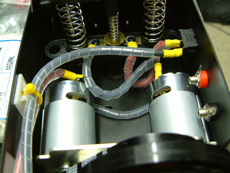
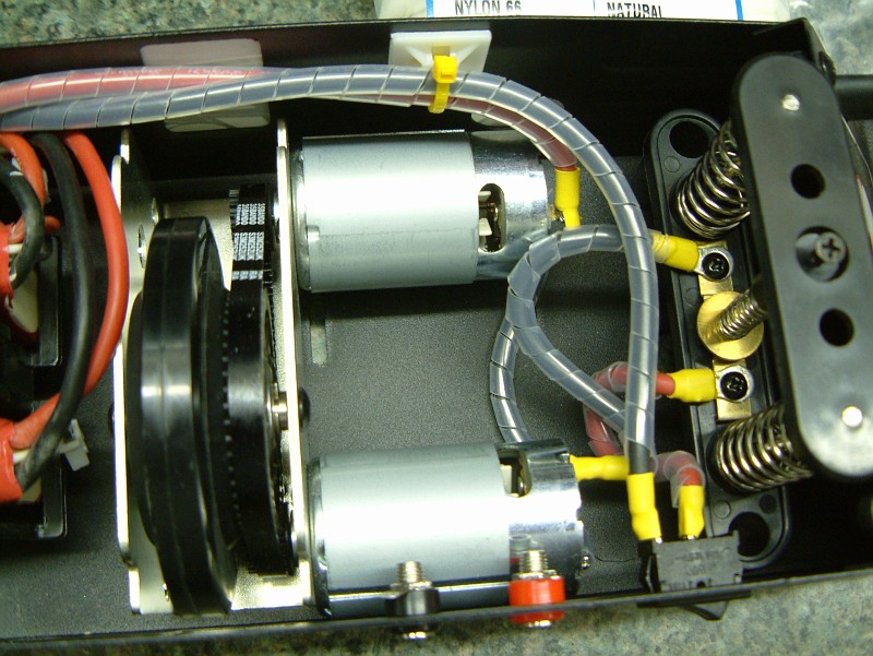
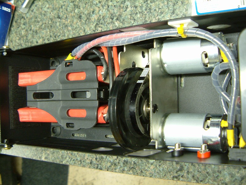
I got my Losi starter box last week, from the start I heard what a turd the stock wiring and white plastic connectors are. I had two extra Pro-Tek 2S 15C 4000mAh batteries so I figured they'd go in the box. I was told to expect a meltdown with the stock connectors so I decided to do a little work. What we have here is a new Losi 8ight/T box with Dean's Wet Noodle 12AWG throughout and 2 x Pro-Tek 4000mAh batteries. I think my soldering station has now more than paid for itself.  On other tip, with the Losi box to keep the plastic from melting on the plunger contacts, put a couple of washers under the metal taps to help dissipate heat.
On other tip, with the Losi box to keep the plastic from melting on the plunger contacts, put a couple of washers under the metal taps to help dissipate heat.
Last edited by rearviewmirror; 01-29-2009 at 08:38 PM.
 01-29-2009, 08:41 PM
#2
Tech Rookie
very nice!! how long did it take to do all this?
01-30-2009, 05:11 AM
#3
About 2 1/2 hours total, I was by no means going fast, and I did a lot of measuring and basically worked it off a drawing I made taking it all apart.
A guy on our local forum recommend getting rid of the plunger switch, well not getting rid of, but eliminating the flow of high current through it and instead having it power a relay which would then fire up the motors. I'm working out how to wire in a relay today.
A guy on our local forum recommend getting rid of the plunger switch, well not getting rid of, but eliminating the flow of high current through it and instead having it power a relay which would then fire up the motors. I'm working out how to wire in a relay today.
01-30-2009, 05:58 AM
#4
awesome job!
what kind of soldering station did you get?
what kind of soldering station did you get?
01-30-2009, 06:28 AM
#6
I did the same thing to my losi box. I soldered all the connections but I am using a 12 volt gel cell. So far my box hasn't let me down.
01-30-2009, 06:33 AM
#7
I would like to have a discussion on wiring in a relay to the box so current isn't passed through the ON/OFF switch and plunger switch. Rather those would be required to work together to send the signal to the relay which would then handle the high current the motors draw. This would help address some of the weak points in the box, those being the plunger switch and the ON/OFF switch.
Seriously, if anyone has any ideas on a simple way to wire this up please post up.
Seriously, if anyone has any ideas on a simple way to wire this up please post up.
01-30-2009, 06:51 AM
#8
If you are looking to put a relay why not look at car stero kits for amps and put in a big fuse to handle the power?
01-30-2009, 06:53 AM
#9
Yep.. that's an option. Just a regular car starter relay or headlight relay should do the trick as well. Just trying to figure out how to utilize two lipo batteries in series to be wired to the relay then provide the main circuit for the motors.
01-30-2009, 11:00 AM
#10
I would like to have a discussion on wiring in a relay to the box so current isn't passed through the ON/OFF switch and plunger switch. Rather those would be required to work together to send the signal to the relay which would then handle the high current the motors draw. This would help address some of the weak points in the box, those being the plunger switch and the ON/OFF switch.
Seriously, if anyone has any ideas on a simple way to wire this up please post up.
Seriously, if anyone has any ideas on a simple way to wire this up please post up.
01-30-2009, 11:06 AM
#11
I don't know about a relay but I did see a box once that had a dead band bush button switch mounted under the plunger switch, so that when the plunger was puched down it would activate the switch. It used the center shaft of the plunger switch to activate the push button switch. When the plunger is pushed down the center shaft protrudes below the plastics, this was used to push the button. It completely eliminates the plunger switch and looks very clean. I'm sure you could find a high capactiy push botton switch that would be suitable.
01-30-2009, 11:08 AM
#12
Here I found a link to what i'm talking about. It was an old xtm starter box.
here is the switch
http://www.hobbypeople.net/gallery/146057.asp
you can kinda see how it is mounted in these
http://www.hobbypeople.net/gallery/146055.asp
http://www.hobbypeople.net/gallery/146053.asp
here is the switch
http://www.hobbypeople.net/gallery/146057.asp
you can kinda see how it is mounted in these
http://www.hobbypeople.net/gallery/146055.asp
http://www.hobbypeople.net/gallery/146053.asp
01-30-2009, 11:41 AM
#13
Here I found a link to what i'm talking about. It was an old xtm starter box.
here is the switch
http://www.hobbypeople.net/gallery/146057.asp
you can kinda see how it is mounted in these
http://www.hobbypeople.net/gallery/146055.asp
http://www.hobbypeople.net/gallery/146053.asp
here is the switch
http://www.hobbypeople.net/gallery/146057.asp
you can kinda see how it is mounted in these
http://www.hobbypeople.net/gallery/146055.asp
http://www.hobbypeople.net/gallery/146053.asp
