


 4Likes
Speed Passion F1 car - The SP1


 04-18-2013, 10:14 AM
#122
So F104 rims work?
04-18-2013, 01:02 PM
#124


 04-19-2013, 08:56 PM
#128
Step 2

Built - remove the flashing the the ball again. Run the screw through the lock nut a couple times to make sure it will snug up. Don't over tighten the pillow ball retainer screws. Don't over tighten the pillow ball assembly to the chassis.

Don't freak out, the pod plate is thinner than the main chassis, just make sure pod pivots and rotates free in every direction with no binding.


 04-19-2013, 09:17 PM
#131
Add the opposite side bearing, retainer, spacer and wheel adapter.

With the axle locked down, lets build the diff. Pretty straight forward.

Diff was easy to adjust, just slide on some spare rims, check for slip and then put the rest of the wheel adapter together.


With the axle locked down, lets build the diff. Pretty straight forward.

Diff was easy to adjust, just slide on some spare rims, check for slip and then put the rest of the wheel adapter together.


 04-19-2013, 09:28 PM
#133
Now mount the lower arms per the original instructions. Mine are mounted in the 190mm config: outer hole in the plate matched to inner hole (next to the indicator mark) in the lower arm. The instructions show the assembly in the 200mm config. Add extra 2mm shims under each arm mount point and use 10mm screws in the front mount to make up for the 2mm lost to the spacer. The screw needs to go in 4mm and only 4mm or the caster plate will not mount correctly from the top.

This is where I left off for now. Good luck with your build.

This is where I left off for now. Good luck with your build.
Last edited by liljohn1064; 04-20-2013 at 08:00 PM.
04-20-2013, 05:32 PM
#134
Picking up where I left off. When putting in the upper ball retainer, do not over tighten and strip it. I had to CA the wrench to the part, turn it out, break it off the wrench and then notched both of them to be able use a screw driver just like the CRC cars.

Inline was my choice.

Do NOT add more shims here to decrease the ride height.

Installed! The front end is done. I found that the recommended gap for the front tie rods @ 23 + mm is wrong, too much toe in. Mine are currently at 21.7 or so and now have a little toe out.

Inline was my choice.

Do NOT add more shims here to decrease the ride height.

Installed! The front end is done. I found that the recommended gap for the front tie rods @ 23 + mm is wrong, too much toe in. Mine are currently at 21.7 or so and now have a little toe out.

Last edited by liljohn1064; 04-20-2013 at 07:58 PM. Reason: correction
04-20-2013, 05:39 PM
#135
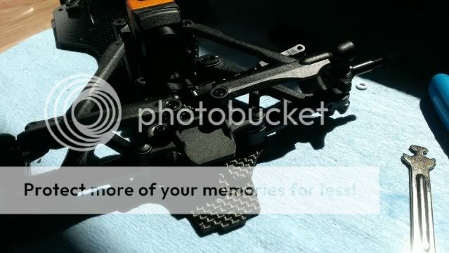
Spring retainer/battery stop install. I threaded the retainers all the way onto the 10mm screw. The springs snap on real nice. Just touching the spring, my gap from the top of the retainer to the brace was about 1.5mm for preload.

Damper tube and upper pod brace assembled.

Installed along with the damper tube and upper pod/damper brace. I missed a couple of pictures in between here, sorry.


Damper tube and upper pod brace assembled.

Installed along with the damper tube and upper pod/damper brace. I missed a couple of pictures in between here, sorry.
