


Post How can i build a R/C car (possible) without using a kit?
 07-10-2011, 11:26 AM
#46
Have a look at the build manuals of a few different RC cars. It should hopefully give you a better understanding of how they work. Direct drive pan cars are the least complicated and if all you want it to do is have it move and steer, can be simplified even further by eliminating the suspension and probably a few other things. I would think the more you simplify the car, the less impressive it will be as a project though.
anyway, here are a few manuals to look over. I'm not sure any show the electronic components installed, but you can find all sorts of pictures here that show some nice wiring jobs.
CRC GenXL - 1/12 scale direct drive pan car: http://www.teamcrc.com/crc/downloads...ete_manual.pdf
TOP Photon - 1/10 scale 4wd belt driven touring car: http://www.petitrc.com/reglages/top/...ton_Manual.pdf
Team Associated B44 - 1/10 scale 4wd shaft driven buggy: http://www.greathobbies.com/manuals/...060_manual.pdf
 07-10-2011, 12:09 PM
#47
Have a look at the build manuals of a few different RC cars. It should hopefully give you a better understanding of how they work. Direct drive pan cars are the least complicated and if all you want it to do is have it move and steer, can be simplified even further by eliminating the suspension and probably a few other things. I would think the more you simplify the car, the less impressive it will be as a project though.
anyway, here are a few manuals to look over. I'm not sure any show the electronic components installed, but you can find all sorts of pictures here that show some nice wiring jobs.
CRC GenXL - 1/12 scale direct drive pan car: http://www.teamcrc.com/crc/downloads...ete_manual.pdf
TOP Photon - 1/10 scale 4wd belt driven touring car: http://www.petitrc.com/reglages/top/...ton_Manual.pdf
Team Associated B44 - 1/10 scale 4wd shaft driven buggy: http://www.greathobbies.com/manuals/...060_manual.pdf
anyway, here are a few manuals to look over. I'm not sure any show the electronic components installed, but you can find all sorts of pictures here that show some nice wiring jobs.
CRC GenXL - 1/12 scale direct drive pan car: http://www.teamcrc.com/crc/downloads...ete_manual.pdf
TOP Photon - 1/10 scale 4wd belt driven touring car: http://www.petitrc.com/reglages/top/...ton_Manual.pdf
Team Associated B44 - 1/10 scale 4wd shaft driven buggy: http://www.greathobbies.com/manuals/...060_manual.pdf
I know this looks impossible for me but i want to make something like this:
or

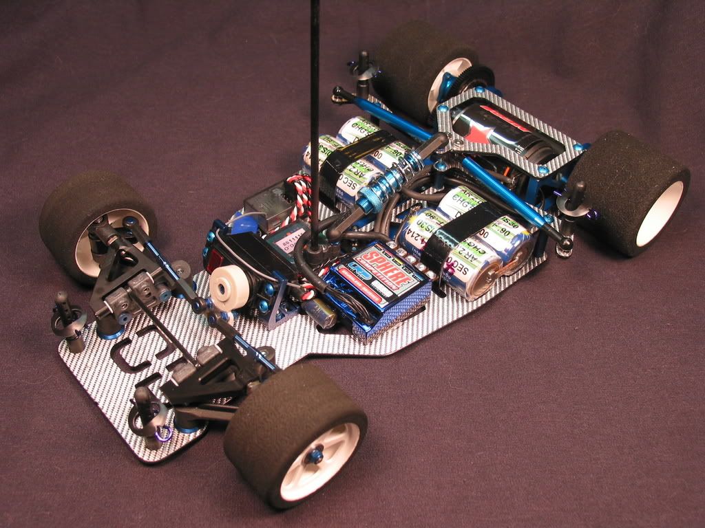
what i cant understand is how the servo is connected to the front wheel and how is motor connected to the rear ones(like the names of the parts etc.)
Thanks
Last edited by soldier16; 07-10-2011 at 01:05 PM.
07-10-2011, 01:13 PM
#48
Thanks for the link with the wiring pictures.
I know this looks impossible for me but i want to make something like this:
http://i245.photobucket.com/albums/g...e/IMG_0015.jpg
or
http://www.comparecenter.com/images/.../IMG_9526m.jpg
what i cant understand is how the servo is connected to the front wheel and how is motor connected to the rear ones(like the names of the parts etc.)
Thanks
The motor is attached to a motor mount. On the shaft of the motor is a pinion gear that meshes with the spur gear that is attached to the axle. On those pan cars, there is a ball differential assembly that the spur gear is actually the central component of.
Last edited by locked; 07-10-2011 at 02:29 PM.
07-10-2011, 01:22 PM
#49
You don't need cad, start with a packet of bendy straws and a roll of cello tape to mock up a tube chassis, or 1.5/2mm copper rod and cello tape. Then make a jig out of some 12mm ply wood, use a router to cut slots into this to lay out the base of the tube chassis, so that its level and square so there is no tweak. Using your bendy straws as templates, use a brake line tube bender to shape each section of the tube chassis, use a dremel or round file to make a C shape in the end of the tube for a snug fit before welding or brazing.
")
I've re-read this thread and all the replies following my post and I must say some of you guys are giving the O.P. the wrong advice. You're advising him from the standpoint that you've ALL built RC cars from kits, you ALL have good knowledge of how they work, but are blatantly overlooking the fact that the O.P. doesn't have that same experience!
Let's be fair in our comments and suggest he either buy a kit and build it, or buy a cheap used RC car and disassemble/reassemble it so he at least gains the most basic understanding of what's involved, before undertaking a major project like building a car from scratch.
I'm all for "DIY", but let's be logical in our suggestions or the poor guy will blow a lot of money on parts & radio equipment only to be overwhelmed and have little to show for it except frustration.
07-10-2011, 01:42 PM
#50

Thanks for the link with the wiring pictures.
I know this looks impossible for me but i want to make something like this:
or
what i cant understand is how the servo is connected to the front wheel and how is motor connected to the rear ones(like the names of the parts etc.)
Thanks
I know this looks impossible for me but i want to make something like this:
or
what i cant understand is how the servo is connected to the front wheel and how is motor connected to the rear ones(like the names of the parts etc.)
Thanks
I you plan to design your own car you should at least do some research and find out how the basics of auto design.
07-10-2011, 02:12 PM
#51
i have a 27mhz, 3channel radio at home.
so maybe finding a kit compatible with that is the way to go(except the kits are quite expensive in UK)?
so maybe finding a kit compatible with that is the way to go(except the kits are quite expensive in UK)?
07-10-2011, 02:16 PM
#52
Like many others, this is not to put you off. But why RC?
You are trying to design something that you seem to be totally unfamiliar with, and without the tools that will do the work (say, jigsaw table, drill press, lathe etc).
Are you still planning to include this as a portfolio type of thing for your eng. school application? Because you mentioned that you want to design a 1/12 scale pan car (the pictures you posted).
For what you are trying to achieve and the access to tools and resources, it may be too simple of a project. I say this because, what are the main components of a pan car? front end, centre shock, rear pod, axle and diff unit, and a plate chassis. Out of those components what can you realistically "build"? It seems like just the chassis itself and a few minor parts.
And even then, it's still a car that is basically put together with a bunch of different parts, not really achieving the 'engineering' part of the project.
But if this hobby is something that you would like to pursue, go ahead and get a proper kit, build a running car, learn about how everything works together etc etc. Then it will give you the experience and knowledge of these cars that you simply cant search on the internet and grasp overnight.
Again I hope this doesn't come across the wrong way.
07-10-2011, 02:24 PM
#53
Thanks for the link with the wiring pictures.
I know this looks impossible for me but i want to make something like this:
or
what i cant understand is how the servo is connected to the front wheel and how is motor connected to the rear ones(like the names of the parts etc.)
Thanks
I know this looks impossible for me but i want to make something like this:
or
what i cant understand is how the servo is connected to the front wheel and how is motor connected to the rear ones(like the names of the parts etc.)
Thanks
07-10-2011, 02:30 PM
#54
If he had access to a school workshop that had a lathe and milling machine, he could build all of it, things like the steering would need to be a more simple design, but it is certainly doable. Mostly this is likely the wrong forum and the wrong people to be asking advice from, the OP really needs to talk to people WHO MAKE SCRATCH cars, because it is really not all that hard to do. IT is about trying to do things as simple and as easy as you can.
07-10-2011, 03:32 PM
#55
Tech Adept
I think these are all fair comments and he should take them into consideration, but if he wants do something simple as a project its definately do-able, obviously experience does help but if hes not interested in rc then???
The pictures youve posted are not really do-able on a budget and if you can afford to pay for the cutting of the carbon etc etc by the time youve paid out it would be cheaper to buy it new.
I'll pm you with a uk site where you can look to see if you can get some decent 2nd hand gear, to stripe down build, customise, get ideas from etc whatever you choose.
Personally I would try and go down to a local club and have a look around 1/10th touring cars are pretty popular in the uk, but there are plenty of 1/10th off road and 1/12th pan car clubs as well.
07-10-2011, 03:46 PM
#56
Tech Fanatic
The top picture is a 1/12th scale, you live in England !! Home of Schumacher racing, try to find some pictures or exploded diagram of their C car or SPC car, maybe even contact them for those.
They used a blade suspension arm system in front which you could duplicate easily with any material.
You seem to want to have the servo connected to the motor, those are 2 different things and are not connected at all.
One the servo is for steering, the other, the motor is for going forward or backward.
I used to make my chassis in the 80s and I did not have lathe or specialised tools, I bought a few parts and used spares for other models.
One thing that you should do is go to your local track and have a chat and explanations by the guys there as to how a model car works.
07-10-2011, 08:57 PM
#57
It's one thing to build a kit, or even throw together parts from several kits, without understanding basic suspension geometry. If you don't understand the basics, you won't understand what you should be doing. Take a look at this thread to get an idea of what you need to understand before attempting your own designs.
http://www.physicsforums.com/showthread.php?t=326355
If all you plan on doing is building a kit, that's really not teaching you anything except mechanical aptitude, and perhaps craftsmanship. But, having a working 3D model can help you visualize how suspension geometry works.
Mastering a CAD program, while worthwhile for an engineering education, isn't really going to help you figure out *what* you should be drawing. Now, if you want to build a kit, and re-draw the parts in CAD to help you figure out the geometry, that would be a good start.
07-10-2011, 11:07 PM
#58
It's one thing to build a kit, or even throw together parts from several kits, without understanding basic suspension geometry. If you don't understand the basics, you won't understand what you should be doing. Take a look at this thread to get an idea of what you need to understand before attempting your own designs.
http://www.physicsforums.com/showthread.php?t=326355
If all you plan on doing is building a kit, that's really not teaching you anything except mechanical aptitude, and perhaps craftsmanship. But, having a working 3D model can help you visualize how suspension geometry works.
Mastering a CAD program, while worthwhile for an engineering education, isn't really going to help you figure out *what* you should be drawing. Now, if you want to build a kit, and re-draw the parts in CAD to help you figure out the geometry, that would be a good start.
http://www.physicsforums.com/showthread.php?t=326355
If all you plan on doing is building a kit, that's really not teaching you anything except mechanical aptitude, and perhaps craftsmanship. But, having a working 3D model can help you visualize how suspension geometry works.
Mastering a CAD program, while worthwhile for an engineering education, isn't really going to help you figure out *what* you should be drawing. Now, if you want to build a kit, and re-draw the parts in CAD to help you figure out the geometry, that would be a good start.
Using the pan car as example and the most simple in steering design a rectangular block with a right angle to catch the steering rods, the Op could design a number of blocks using various amounts of castor and camber and test them out to see what performs better. All you would need to do this is a basic pan car some blocks of delrin or aluminum and basic tools, a file, a fine saw and a drill.
You could start with no camber and castor and then slowly add in 1deg of one the then other, then both, testing each one as he goes and noting lap times over a 15 lap run. To change the camber, just drill the axle hole at a 1deg angle, castor, king pin hole on an angle. Sure its rough, but what you are wanting to find out, is the effect that changes in these have, and in a 1/12 pan car it would be pretty dramatic in the effect it has on how well the car steers.
Thinking about it, this would be a pretty cool project for anyone doing high school level machine shop or mechanics, and for someone doing higher education, i am sure there is a good summer project and paper to be had from it for a few extra credits.
07-10-2011, 11:34 PM
#59
As for costs, the above can be done ultra cheep, RC Speed do rear pan car axle sets with spur gear for like 15 or 20 bucks including bushings and ball diff, and steering blocks for like 3 bucks, go to a local scrap merchant or sheet metal works and raid their scrap bin for a piece of plate big enought to cut out a chassis. There you have it, $30 buck roller 1/12 pan car.
07-11-2011, 12:46 AM
#60
So, which software would be better for a beginner Solidworks or Autodesk?
Thanks
Thanks