


 55Likes
Xray X1 front indepndent disc brakes
 02-07-2021, 02:42 PM
#1
Hi all,
Thanks for popping by.
So, the concept is verrrry simple, honing the car untill it has some decent braking power. I guess you can say, this is another "Pandemic Special". I started working on this when they announced that the winter season of carpet racing will be cancelled, so now I just hope that I'll be ready with it by the time the open air rc tracks will open.
Every car that accelerates, and decelerates, has it's CoG moving from rear to front and vice versa. The majority of braking power is beeing generatad on the front axle ( around 70%). Now, in the realms of RC racing, the 2wd cars have been robbed of this braking power. On free trainig sessions this is beautifully visible, where the 21.5t motored F1 is faster everywhere then the same motored touring car, save the braking distance, and obviously that results in slower laptimes, Now, I'm restless. By nature. I just could not accept the reality, that this amazing, nimble rc model has it's limitations in this regard. Ofcourse, you can drive it so that this is not as much of a hindrance, but started this project for the sake of the experiences in iterative design, testing, simulating and cad designing ( also, learning 3d printing). Altho I am fully aware, that this technology will be most probably banned everywhere, one can dream I think this wil make me faster, but not that much that I can make ETS A main, so no worries there.
About the design.
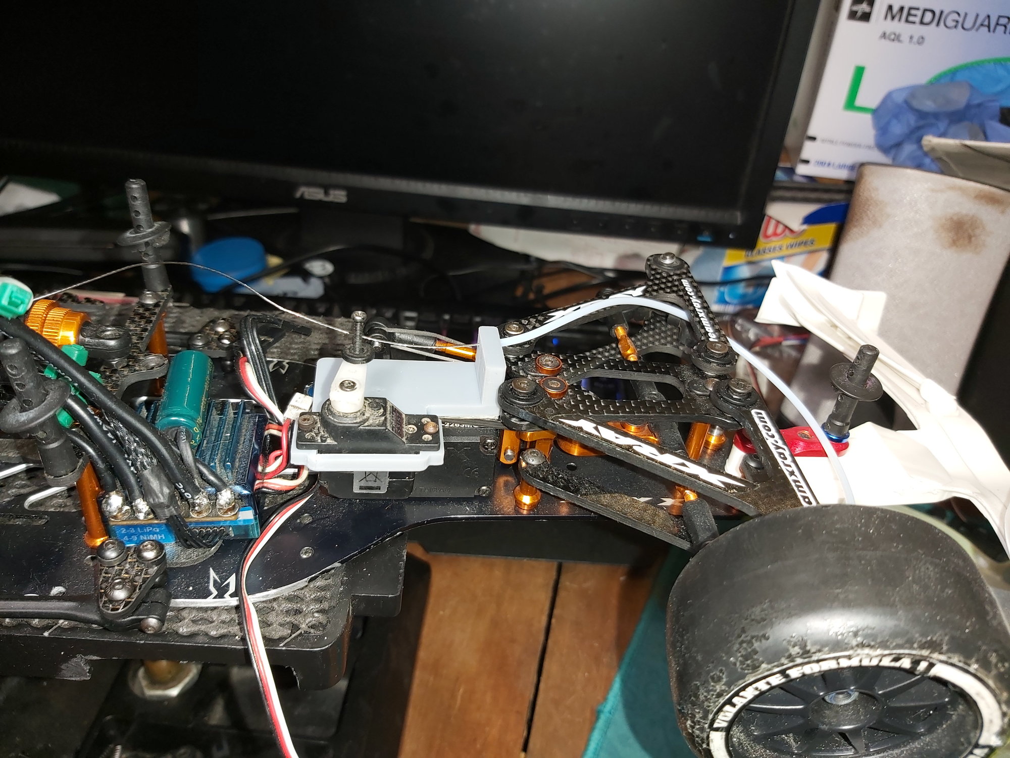
I will state, that I am not an engineer (yet) but I have some life experiences, so I kinda had an idea to go by. Started out with the concept of one fix brake pad, and a moving (floating) brake disc, but that prooved useless due to chronic lack of space. So, that concept flew out on the window. I experimented with all sorts of solutions, and I came up with what seems like is going to be the winner, a double piston co-floating system. Co-floating, because the pistons are floating within the wheel hub ( brake hub if you will), and the action of the servo's pull on the cable is what actuates both pistons, whose movements are opposite of eachother. This iteration on the video is iteration no. 12, and it is by far not the final one. the 13.th has already been printed, but I just didn't have the time yet to assemble it. Due to tight space constraints, I had to redesign the whole front hub, because the brake disc would have not had any space to go with. So, I had to rob 2mm of space from the excisting hub, because ( and this was probably the biggest challege) the wheelshaft is stationary, meaning the damned brake disc has to be able to rotate compared to the shaft and also rotate true, and this was a head scratcher. I ended up incorporating a slim bearing, using that to support the brake disc. Currently I use 0.8mm thick steel wire, but I intend to replace it to something a bit more conforming. already have the candidate, I'll post the results once I have it.
Servos are a pain. I used 2 Futaba S3117's, and they both burned up on the bench ( that was an oopsie). So now I've ordered some stronger ones, hopefully they'll arrive from china in this century ( damned pandemic slowed everything down) I bought a pair of GDW DS031MG servos, and I just hope those will hold. I will also add a spring dampening to the brake system, so that the small servo will have some chance to survive. If I'll find some extra time on my hand, I'll design the mechanism for one servo front brake, but there I have to solve the independent adjustability of the brake wires.
I'll post any and every advancements on this as I go by, My cnc carbon mill is in it's last stage of beeing manufactured(own design), so hopefully I can make my carbon brake discs soon, and make the other parts out of some more durable materials ( this basic resin is useless for mechanical parts). I do intend to sell this system as a kit, but I sincerely doubt, that anyone will buy it simply because they will be banned everywhere ( nonetehless, let me know if you guys are interested).
I do have some other plans to enhance the F1 (Carbon rear shaft), I'll post them as well in due time.
The video of the current state of the project:
You'll have to excuse the foreign language, transcript can be found in the description.
Thanks for popping by.
So, the concept is verrrry simple, honing the car untill it has some decent braking power. I guess you can say, this is another "Pandemic Special". I started working on this when they announced that the winter season of carpet racing will be cancelled, so now I just hope that I'll be ready with it by the time the open air rc tracks will open.
Every car that accelerates, and decelerates, has it's CoG moving from rear to front and vice versa. The majority of braking power is beeing generatad on the front axle ( around 70%). Now, in the realms of RC racing, the 2wd cars have been robbed of this braking power. On free trainig sessions this is beautifully visible, where the 21.5t motored F1 is faster everywhere then the same motored touring car, save the braking distance, and obviously that results in slower laptimes, Now, I'm restless. By nature. I just could not accept the reality, that this amazing, nimble rc model has it's limitations in this regard. Ofcourse, you can drive it so that this is not as much of a hindrance, but started this project for the sake of the experiences in iterative design, testing, simulating and cad designing ( also, learning 3d printing). Altho I am fully aware, that this technology will be most probably banned everywhere, one can dream
I think this wil make me faster, but not that much that I can make ETS A main, so no worries there.About the design.
I will state, that I am not an engineer (yet) but I have some life experiences, so I kinda had an idea to go by. Started out with the concept of one fix brake pad, and a moving (floating) brake disc, but that prooved useless due to chronic lack of space. So, that concept flew out on the window. I experimented with all sorts of solutions, and I came up with what seems like is going to be the winner, a double piston co-floating system. Co-floating, because the pistons are floating within the wheel hub ( brake hub if you will), and the action of the servo's pull on the cable is what actuates both pistons, whose movements are opposite of eachother. This iteration on the video is iteration no. 12, and it is by far not the final one. the 13.th has already been printed, but I just didn't have the time yet to assemble it. Due to tight space constraints, I had to redesign the whole front hub, because the brake disc would have not had any space to go with. So, I had to rob 2mm of space from the excisting hub, because ( and this was probably the biggest challege) the wheelshaft is stationary, meaning the damned brake disc has to be able to rotate compared to the shaft and also rotate true, and this was a head scratcher. I ended up incorporating a slim bearing, using that to support the brake disc. Currently I use 0.8mm thick steel wire, but I intend to replace it to something a bit more conforming. already have the candidate, I'll post the results once I have it.
Servos are a pain. I used 2 Futaba S3117's, and they both burned up on the bench ( that was an oopsie). So now I've ordered some stronger ones, hopefully they'll arrive from china in this century ( damned pandemic slowed everything down) I bought a pair of GDW DS031MG servos, and I just hope those will hold. I will also add a spring dampening to the brake system, so that the small servo will have some chance to survive. If I'll find some extra time on my hand, I'll design the mechanism for one servo front brake, but there I have to solve the independent adjustability of the brake wires.
I'll post any and every advancements on this as I go by, My cnc carbon mill is in it's last stage of beeing manufactured(own design), so hopefully I can make my carbon brake discs soon, and make the other parts out of some more durable materials ( this basic resin is useless for mechanical parts). I do intend to sell this system as a kit, but I sincerely doubt, that anyone will buy it simply because they will be banned everywhere ( nonetehless, let me know if you guys are interested
).I do have some other plans to enhance the F1 (Carbon rear shaft), I'll post them as well in due time.
The video of the current state of the project:
You'll have to excuse the foreign language, transcript can be found in the description.
Last edited by mikeylama; 10-05-2022 at 11:51 AM.
 02-07-2021, 02:47 PM
#2
Some earlier iterations of the design:


02-07-2021, 08:56 PM
#3
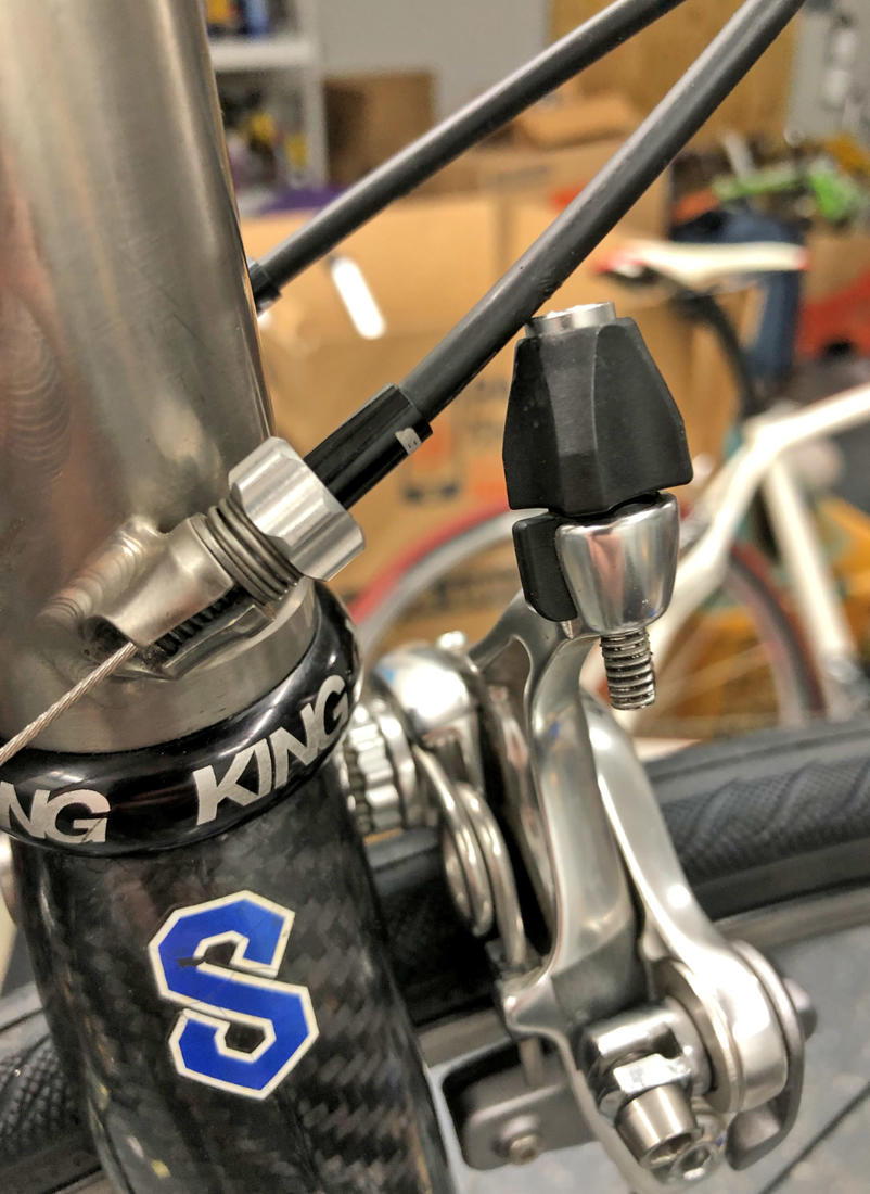
Sorta clever design. Though you can save lots of weight on the cable routing by doing something that is done commonly on road/mountain bikes. Where you only use cable housing from the caliper to the inner suspention mounting point. From there, you would only need a pulley or housing clamp/mount, as the cable can freely run straight to the mini servo (must be a straight pull area)
02-07-2021, 09:01 PM
#4
Also, In handycap 4 wheel mountain bikes, they basically have a similar wire brake system for the front wheels. You don't need 2 servos for the brakes. Both front brakes can be connected by a Y intersection and pulled by a single mini servo
02-07-2021, 10:16 PM
#5
pretty cool. I'm curious, do you know about how much the system weighs?
02-07-2021, 10:32 PM
#6
GT CRUSING , the extremely limited space prohibits any levered design, I tried it, but it is crazily crammed up inside that wheel. The clerance is almost none between the inner wall of the wheel, and the calipper,and is only 1mm betwen the wheel spokes and the outside(inside depend on where you look at it from) brake calipper. However now that I think about it, my design is quite close to this one that you mention, but rotated 90�.
mikel33 , the material used is far beeing the "production" one, for isntance the servo holder will be one unit together with the servo holder carbon piece ( I intend to mill it out of one piece of carbon fiber laminate). The material of the pistons will be either Metamit, PA66GF30 or EN AW 7075 (AZ93 would be a LOT nicer, but that damned thing is almost impossible to acquire for a mortal like me) depends on what I can get, and also if I could make an injection moulding machine or not(then it'll be PA66xxx). Brake disc will be 1mm carbon fiber disc on EN AW 7075 hub( again Magnesium would be nicer), and the whole wheel hub will be either machined out of something, or injection molded ( altho that'll be a challenge to create the mold for that complicated object). In theory I could give you the numbers from the cad design, I have not gone there yet, but if I have to guess, I'd say this will introduce around 30 grams to the car (maybe 40) servos included, witch is fine, because my car was 30g under the weight limit.
mikel33 , the material used is far beeing the "production" one, for isntance the servo holder will be one unit together with the servo holder carbon piece ( I intend to mill it out of one piece of carbon fiber laminate). The material of the pistons will be either Metamit, PA66GF30 or EN AW 7075 (AZ93 would be a LOT nicer, but that damned thing is almost impossible to acquire for a mortal like me) depends on what I can get, and also if I could make an injection moulding machine or not(then it'll be PA66xxx). Brake disc will be 1mm carbon fiber disc on EN AW 7075 hub( again Magnesium would be nicer), and the whole wheel hub will be either machined out of something, or injection molded ( altho that'll be a challenge to create the mold for that complicated object). In theory I could give you the numbers from the cad design, I have not gone there yet, but if I have to guess, I'd say this will introduce around 30 grams to the car (maybe 40) servos included, witch is fine, because my car was 30g under the weight limit.
Last edited by mikeylama; 02-08-2021 at 12:41 AM.
02-08-2021, 12:24 AM
#7
Some of the previous iterations, where I tried to figure out how to actuate the brake( left most white hub was the levered version)

02-08-2021, 12:54 PM
#8

This is the second "front brake" project I've seen. Both.. I found to be amazing.
My thoughts on this were usually around using magnetic braking.. because I felt like I could control that better. Especially for the light loads of a pan car.
Keep it up, I can't wait to see how this goes.
My thoughts on this were usually around using magnetic braking.. because I felt like I could control that better. Especially for the light loads of a pan car.
Keep it up, I can't wait to see how this goes.
02-08-2021, 01:22 PM
#9
This is the second "front brake" project I've seen. Both.. I found to be amazing.
My thoughts on this were usually around using magnetic braking.. because I felt like I could control that better. Especially for the light loads of a pan car.
Keep it up, I can't wait to see how this goes.
My thoughts on this were usually around using magnetic braking.. because I felt like I could control that better. Especially for the light loads of a pan car.
Keep it up, I can't wait to see how this goes.
PLUs, I am not an electric engineer to come up with all the hardware  Also, I quite fancy the idea of a cool-cat loking carbon disc inside the wheel
02-08-2021, 02:14 PM
Also, I quite fancy the idea of a cool-cat loking carbon disc inside the wheel
02-08-2021, 02:14 PM
#11
Aluminium is a non ferrous material, it does not work like that. It does contain a few( 1-2) percent of ferrous contaminatoon usually, but that is very few to be reckoned with.
02-08-2021, 02:32 PM
#12
Suspended
02-08-2021, 02:57 PM
#13
Magnetic braking is something I considered as well, BUT the car is capable of travelling 50 km/h down the straight, and it is 1050 gram of weight, that gives us 96,4506 J of kinetic energy at terminal speed to be reckoned with. That is quite high (frankly I am not sure if those disc brakes will stop the car, everything is a theory untill I can get my hang on that damned CNC mill of mine), and the magnetic field required to stop the car would be so high, that I could not fit the coil onto the hub. It may not looks like it, but there isn't really that much of a space, plus you need the conductive material for the brake disc, that is increases rotating mass that increases it's inertia what in turn decreases acceleration.
02-08-2021, 03:56 PM
#15
https://en.wikipedia.org/wiki/Eddy_current_brake
And because Derek is awesome, here's a demo by Veritasium.
Magnetic braking is commonly used on precision scales, as it has no stiction. It's braking force is also directly related to speed, matching the sort of braking you get from shorting out an electric motor...
Regardless, your system is working :-) and this is a discussion for another place.

