


 4Likes
Tamiya TRF417
 09-28-2011, 03:17 PM
#1936
Tech Adept
Firstly... put the links on the rear holes on the hubs... this will make the steering better, trust me 
Next, with the links the same lengths... adjust your servo sub-trim on your transmitter so the steering is in the middle. If the horn cants more towards the centre of the car, don't worry.
The other option is to length the link between the servo horn and the steering, so it becomes more central.
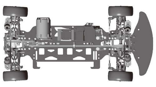
You can actually see in that shot that the bell-cranks are pointing to the left of the car, hence why it looks like the right wheel is steering more to the right.
Just have a play around with it, and get a feel for what adjusting each thing does to the steering.
This weekend I'm on holiday, so I'll try and add some pics to the guide to help.
Regards
Ed
Next, with the links the same lengths... adjust your servo sub-trim on your transmitter so the steering is in the middle. If the horn cants more towards the centre of the car, don't worry.
The other option is to length the link between the servo horn and the steering, so it becomes more central.
You can actually see in that shot that the bell-cranks are pointing to the left of the car, hence why it looks like the right wheel is steering more to the right.
Just have a play around with it, and get a feel for what adjusting each thing does to the steering.
This weekend I'm on holiday, so I'll try and add some pics to the guide to help.
Regards
Ed
Should the bell cranks be absolutely at the center?
Am I wrong, or are the wheel angles on each side different? If so, how can this happen if both links are exactly the same length?
 09-28-2011, 05:44 PM
#1938

You have to zero the servo, then re-attach the servo horn to the servo to get everything similar on both sides ! You will probably endup with more bellcrank showing in one direction or another anyway, just try to minimize the difference as much as possible...
09-28-2011, 05:47 PM
#1939
By the way, did you check your front toe ? It looks way out....
09-28-2011, 06:37 PM
#1940
Thanks a lot, pics would be really helpful.. I am attaching additional pictures after what you mentioned. As you can see, the bell cranks are pointing to the right more than the left now but I still see the right wheel's angle pointing outward more than the left.
Should the bell cranks be absolutely at the center?
Am I wrong, or are the wheel angles on each side different? If so, how can this happen if both links are exactly the same length?
Should the bell cranks be absolutely at the center?
Am I wrong, or are the wheel angles on each side different? If so, how can this happen if both links are exactly the same length?
It can happen if your camber is not identical on both sides<<<<
It can happen if your hinge pin spacers/ roll spacers are not the same on both side.
It can happen if the ball end are not screwed in perfectly square and level.
You can't judge it by eye and especially by a camera pic. You need to pick up camber gauge/ toe in gauge tools to eliminate any human error
 09-28-2011, 08:21 PM
#1941
Tech Adept
09-28-2011, 08:29 PM
#1942
Tech Adept
Hi,
It can happen if your camber is not identical on both sides<<<<
It can happen if your hinge pin spacers/ roll spacers are not the same on both side.
It can happen if the ball end are not screwed in perfectly square and level.
You can't judge it by eye and especially by a camera pic. You need to pick up camber gauge/ toe in gauge tools to eliminate any human error
cambers is identical according to the camber gauge.
Can you elaborate more on the second two points? I am not very familiar with the terminology you used

I am planning to get a hudy measurement kit, but what surprises me is that the two wheels have a different toe angles even though they have same link attachment lengths. Or at least that's what my eye sees, hopefully a measurement proves me wrong.
09-28-2011, 08:53 PM
#1943
cambers is identical according to the camber gauge.
Can you elaborate more on the second two points? I am not very familiar with the terminology you used
I am planning to get a hudy measurement kit, but what surprises me is that the two wheels have a different toe angles even though they have same link attachment lengths. Or at least that's what my eye sees, hopefully a measurement proves me wrong.
By the look of it, make the two steering links a little longer (half a turn each or so), then forget about them.
You then need to adjust either the servo horn postion (by transmitter sub-trim), or the length of the drag link between the steering and servo.
Quite simply, IMO, the manual is not right in regards to the length of the drag link, so this needs to be adjusted to get it right, in combination with the servo horn position. That one link helps to control the position of the steering, in both directions. With the steering off centre, you get the effect you are seeing, with one wheel looking to have more toe than the other.
When I take some pics over the weekend, I'll measure all the link lengths I use as well, and note them down for you.
Don't worry about using lots of sub-trim to get the servo in the right place, I'm running with about 40 points to the right to get the horn where I need (sanwa tranny). It's more critical to get the horn and drag link in the right place than worrying about having a lot of sub-trim on the transmitter.
Regards
Ed
Last edited by TryHard; 09-28-2011 at 08:59 PM. Reason: Typing on an iPhone... Big thumbs issues!
09-29-2011, 03:53 AM
#1944
 09-29-2011, 03:35 PM
#1947
Funny this is exactly how I run my top deck. Makes perfect sense to me. A bit more flex from the chassis also makes sense too. The closer it is to the 416X lipo the better, as it was a better car.
09-29-2011, 10:23 PM
#1949
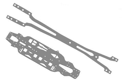
So update will be:
1. Lower deck
2. Upper deck
3. Motor mount
4. Shock mounts
Is this correct?
1. Lower deck
2. Upper deck
3. Motor mount
4. Shock mounts
Is this correct?
09-29-2011, 10:40 PM
#1950
Shock mounts look like a good idea though, and I can see myself getting a second set to mount on my current 7.
Ed