Go Back  R/C Tech Forums > General Forums > Electric Off-Road
Team Associated B6 & B6D thread >

Team Associated B6 & B6D thread

Community
Wiki Posts
Search
Like Tree649Likes

Team Associated B6 & B6D thread

    Hide Wikipost
Old 06-07-2017, 10:46 AM   -   Wikipost
R/C Tech ForumsThread Wiki: Team Associated B6 & B6D thread
Please read: This is a community-maintained wiki post containing the most important information from this thread. You may edit the Wiki once you have been a member for 90 days and have made 90 posts.
 
Last edit by: RCBuddha
Welcome to the B6 Wiki!

Quick links to all the sections on the first page!

Frequently asked questions - the most common questions you may have answered here!

Aftermarket Parts - parts for the B6 and B6D

Tech Tutorials- tuning guides, ball diff and shock building videos and tutorials

How to's and build-specific posts

Team Associated Laydown transmission conversion for B6D:
Laydown conversion

Instruction Manuals:

B6: B6 Manual and setup sheets

B6D: B6D Manual and setup sheets

How to Sand and Seal carbon fiber:
Sanding and sealing carbon fiber
Sanding and sealing carbon fiber 2
Sanding and sealing carbon fiber 3
Sanding and sealing carbon fiber 4

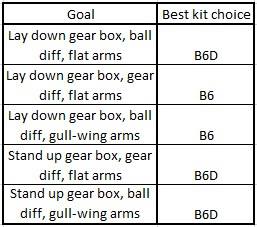
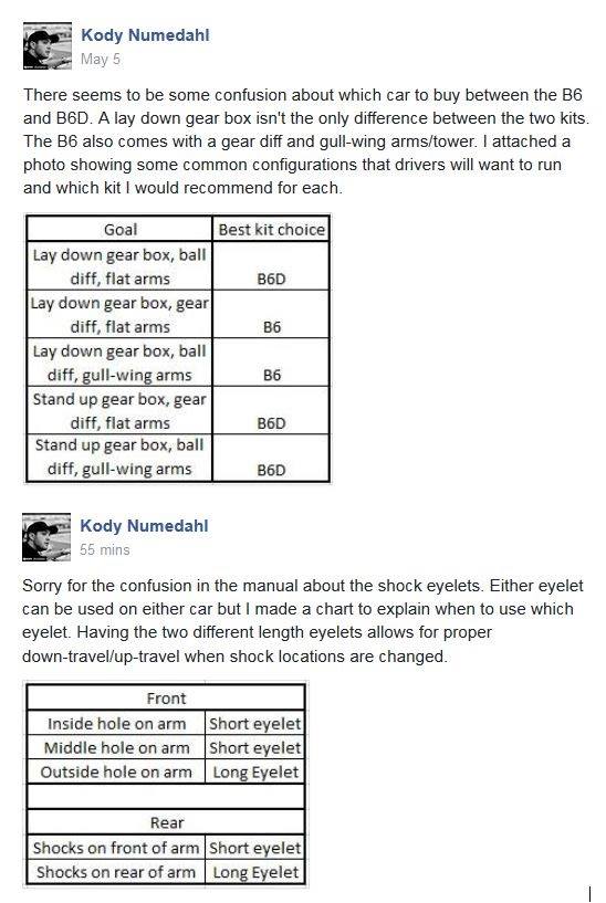
Charts for Quick reference:


1) put inner bearing in hub
2) slide large shim over axle all the way up to the back of the axle
3) slide axle/bone into hub carrier
4) slide small shim onto axle through hub carrier
5) push outter bearing into hub carrier

using that i'm able to put my normal male silverback gorilla wheel nut tightening job and there's no binding. in the pictures that come with the shims (the pic socket posted) it seems like they want you to slide both shims onto the axle before sliding the axle into the hub carrier and like i said, that doesn't work.


I've traditionally done the diff screw head on the left side (driver's side), but have since switched to the Right side (passenger side) regardless of transmission type (3 gear RM vs 3 gear MM and 4 gear MM).

Kdub (Kurt Wenger, former AE designer) had this to say on the matter:

Originally Posted by kdub
I think I count as an authority on the matter. I always run my diff screw on the right side (when sitting "inside" the car). I take off the tire and pull the outer hinge pin to get to the adjustment screw.

The right rear is the way the AE manuals state (or used to state). It really shouldn't matter since you go around turns both left and right.
B6D 3-gear:

Print Wikipost

Thread Tools
 
Search this Thread
 
Old 08-16-2016, 07:36 PM
  #2641  
Tech Fanatic
iTrader: (35)
 
rvrslt1's Avatar
 
Join Date: Jan 2015
Location: Torrance CA
Posts: 968
Trader Rating: 35 (100%+)
Default

From what I understand you can run shocks on front of arms with larger shock bodies and short eyelets.
Kurt will be posting a new set up sheet useing it.
rvrslt1 is offline  
Old 08-16-2016, 07:40 PM
  #2642  
Tech Elite
iTrader: (14)
 
Join Date: Jul 2008
Location: SoCal
Posts: 2,162
Trader Rating: 14 (100%+)
Default

Great now i have to buy kashimas
DG Designs is offline  
Old 08-16-2016, 07:58 PM
  #2643  
Tech Fanatic
iTrader: (35)
 
rvrslt1's Avatar
 
Join Date: Jan 2015
Location: Torrance CA
Posts: 968
Trader Rating: 35 (100%+)
Default

25 bucks and change at LApartshouse.com. Have them on order.
rvrslt1 is offline  
Old 08-16-2016, 08:24 PM
  #2644  
Tech Regular
iTrader: (5)
 
Join Date: Sep 2015
Location: Auburn, CA
Posts: 301
Trader Rating: 5 (100%+)
Default

Originally Posted by Wildcat1971
Reedy, Fantom, Trinity, Schuurspeed are all popular enough. More support from Reedy though. Fantom is nice if you want to custom option the motor
You can't beat the support from Schuur Speed. Ron Schuur has personally answered any question that I have had. That guy must never sleep, I've gotten responses from him very late into the night.
afm223 is offline  
Old 08-16-2016, 11:48 PM
  #2645  
Tech Regular
 
Join Date: Nov 2013
Location: Tucson, AZ
Posts: 425
Default

Originally Posted by Tmack
Gents,

Newbie Question, how do you set and measure shock stroke?

Thanks in advance.
I use a set of digital calipers. You can get them for around $25
Riverbluff is offline  
Old 08-17-2016, 05:45 AM
  #2646  
Tech Addict
iTrader: (14)
 
rimracker's Avatar
 
Join Date: Sep 2011
Location: Southington CT
Posts: 695
Trader Rating: 14 (100%+)
Default

Originally Posted by Jmuck69
Initially the part you might want to consider is the aluminum D Block. Allows you to use the inserts and opens up more tuning possibilities.
Looking around for info on the D block. Specifically toe angles when changing the inserts in both the C and D. I get the one in the manual for the C, but the toe angle would change with the D if you move it out of the center, no?
rimracker is offline  
Old 08-17-2016, 05:49 AM
  #2647  
Tech Champion
iTrader: (170)
 
Matt Trimmings's Avatar
 
Join Date: Jun 2006
Location: Tucson AZ
Posts: 6,272
Trader Rating: 170 (100%+)
Default

Originally Posted by rimracker
Looking around for info on the D block. Specifically toe angles when changing the inserts in both the C and D. I get the one in the manual for the C, but the toe angle would change with the D if you move it out of the center, no?
Everything moves either .5-1 increments depending on which pill you use and where its located. Center dot pill in the C/D mount is 3° toe and 1° anti squat. Use that as a reference point and adjust away.
Matt Trimmings is offline  
Old 08-17-2016, 05:53 AM
  #2648  
Tech Addict
iTrader: (14)
 
rimracker's Avatar
 
Join Date: Sep 2011
Location: Southington CT
Posts: 695
Trader Rating: 14 (100%+)
Default

Originally Posted by Matt Trimmings
Everything moves either .5-1 increments depending on which pill you use and where its located. Center dot pill in the C/D mount is 3° toe and 1° anti squat. Use that as a reference point and adjust away.
Thanks, I guess what was throwing me off was on the set up sheets above the C and D mount it said 1 or .5 degree.
rimracker is offline  
Old 08-17-2016, 06:00 AM
  #2649  
Tech Champion
iTrader: (170)
 
Matt Trimmings's Avatar
 
Join Date: Jun 2006
Location: Tucson AZ
Posts: 6,272
Trader Rating: 170 (100%+)
Default

Originally Posted by rimracker
Thanks, I guess what was throwing me off was on the set up sheets above the C and D mount it said 1 or .5 degree.
You choose which pill you are using and then the placement of the hole within the C/D mount. It is very adjustable and confusing at first.
Matt Trimmings is offline  
Old 08-17-2016, 06:06 AM
  #2650  
Tech Apprentice
 
BigChris in PA's Avatar
 
Join Date: Aug 2016
Location: Shavertown, Pa
Posts: 93
Default

Postman brought my B6 to me yesterday. I started about 7pm and finished about 11pm.
Installed Bi Metal pucks on the gear diff and Exotek slipper eliminator right out of the box.

Couple things I noticed, I'll break em down into fitment and manual errors.

Fitment issues:
1) I studied and triple checked the orientation of the steering rack. I'm 95% sure I've got his right. Bag 1 Step 1 wants a 2mm spacer under the ballstud on the bell crank. I installed them and then ultimately removed them b/c I am not stoked with the amount of steering "throw" The ball stud/ball cup crashes into part 91667. If I compare the steering throw of my B5M FL to the B6 side by side, the B5M has got tons more. See the pic below. Maybe I'm doing something wrong, please advise.

2) Somebody else mentioned it here, but one of my turnbuckles isn't threaded correctly. It's on the LH threaded end, it looks threaded, but upon closer inspection, the threads have no pitch to them. They're sorta just ribs. No amount of turning (in either direction) will get the ball cup to screw on. I was fortunate to have a 48mm Factory Team Ti set in spare parts inventory for my B5M I "borrowed" to complete the build.

Manual errors:
Bag 5-8 step 1: shows no spacer under the ball stud. Yet in Bag 5-8 step 2 and step 3 one can clearly be seen in the rendering. There are also 2mm spacers included in these part bags. I installed them as shown in the Bag 5-8 step 2.

Bag 11-14 step 8: calls for 8 M3x10mm FHCS to mount the tranny and the chassis brace. The hardware kit includes 6 M3x10 FHCS for the tranny, and 2 M3x14 for the chassis brace (I think, they might have been M3-12s. At any rate, there were 2 that were definitely longer)

Any advice on the steering rack would be helpful. It looks like if you install the rack upside down vs what the manual wants it would buy me more clearance. I fear this however would have adverse affects on the steering geometry

edit "not enough posts to include a url to other site" so sorry no pic, which is kinda weak.
BigChris in PA is offline  
Old 08-17-2016, 06:15 AM
  #2651  
Tech Champion
iTrader: (170)
 
Matt Trimmings's Avatar
 
Join Date: Jun 2006
Location: Tucson AZ
Posts: 6,272
Trader Rating: 170 (100%+)
Default

Originally Posted by BigChris in PA
Fitment issues:
1) I studied and triple checked the orientation of the steering rack. I'm 95% sure I've got his right. Bag 1 Step 1 wants a 2mm spacer under the ballstud on the bell crank. I installed them and then ultimately removed them b/c I am not stoked with the amount of steering "throw" The ball stud/ball cup crashes into part 91667. If I compare the steering throw of my B5M FL to the B6 side by side, the B5M has got tons more. See the pic below. Maybe I'm doing something wrong, please advise.
pay close attention to the orientation of the rack. If its upside down or backwards then the ball stud could hit the bellcrank. With it properly there is no way with 2mm of spacing. You can email me a pic if you have other questions. Check your pm.
Attached Thumbnails Team Associated B6 & B6D thread-rack.png  

Last edited by Matt Trimmings; 08-17-2016 at 06:29 AM.
Matt Trimmings is offline  
Old 08-17-2016, 06:25 AM
  #2652  
Tech Champion
iTrader: (170)
 
Matt Trimmings's Avatar
 
Join Date: Jun 2006
Location: Tucson AZ
Posts: 6,272
Trader Rating: 170 (100%+)
Default

Originally Posted by BigChris in PA

Any advice on the steering rack would be helpful. It looks like if you install the rack upside down vs what the manual wants it would buy me more clearance. I fear this however would have adverse affects on the steering geometry
Thanks for the pic. It is definitely on backwards. Pay close attention, the manual references which side goes forward and you can also see which side is up / down.
Matt Trimmings is offline  
Old 08-17-2016, 07:12 AM
  #2653  
Tech Apprentice
 
BigChris in PA's Avatar
 
Join Date: Aug 2016
Location: Shavertown, Pa
Posts: 93
Default

Originally Posted by Matt Trimmings
Thanks for the pic. It is definitely on backwards. Pay close attention, the manual references which side goes forward and you can also see which side is up / down.
Thanks Matt, it was getting late last night and I musta had a brain fart. I'll check it again when I get home from work.
BigChris in PA is offline  
Old 08-17-2016, 08:24 AM
  #2654  
Tech Fanatic
iTrader: (11)
 
Orion_2kTC's Avatar
 
Join Date: Sep 2010
Location: Lincoln, NE
Posts: 942
Trader Rating: 11 (100%+)
Default

Originally Posted by DG Designs
Great now i have to buy kashimas
I'm surprised the new kit didn't come with them. I will have to as well, they came with the b5ce and were super smooth.
Orion_2kTC is offline  
Old 08-17-2016, 08:26 AM
  #2655  
Suspended
iTrader: (61)
 
Join Date: Jan 2011
Posts: 4,121
Trader Rating: 61 (100%+)
Default

I love the kashimas.

I know more than one person who doesn't like them

I also like the gold shafts over the chrome.
Socket is offline  


Contact Us - Archive - Advertising - Cookie Policy - Privacy Statement - Terms of Service -

Copyright © 2024 MH Sub I, LLC dba Internet Brands. All rights reserved. Use of this site indicates your consent to the Terms of Use.