


Helical vs Straight cut gearing
 06-23-2015, 12:43 AM
#1
Figured I'd start a constructive debate on gear design.
With that being said...
I have been doing some thinking and I personally don't understand why hasn't anyone made a good helical gear type for center diff or typical spurs and pinions?
The main known down side to helical cut is a slight loss in efficiency vs a like sized strait cut gear, but they can take much more power input without the noise and deliver that power much more smoothly without the slop. Setting gear mesh would be a load easier and theoretically one should be able to produce a helical cut spur and pinion that is 1/3 the width of a standard cut set and retain optimal durability. The reduced width would also make up for the efficiency loss and even help with less rotational mass, thus further reducing parasitic loss in the drive line. Helical gear self clear debris better as well.
Here is an info source for some to look at > Helical Gears vs. Spur Gears
Anyone,... thoughts?
 06-23-2015, 02:12 AM
#2
Well first, I don't know if its just the picture you have posted, but if that is the orientation needed for helical cut gears, I don't see how it would be possible to have the motor drive a gear like that in a current layout. Could it be done? Maybe, but a lot of unnecessary redesigning would be required. (Edit) So it looks like there are parallel axis helical gears, but from what I can tell if you need to flip the pinion around it wouldn't work, so every pinion manufacture would have to have two full sets of pinions available. Still completely unnecessary.
Second, 4wd SCT and 1/8 scales are way over powered anyway, so a slight improvement in drive train efficiency wouldn't matter. The gears we have work well enough, no real need to change the way the gears are designed just because helical cut gears might be marginally better.
Third, your link goes to nothing.
Last edited by Mantis Toboggan; 06-23-2015 at 02:23 AM.
06-23-2015, 02:58 AM
#3
I'd say the main downside to helical gears is the thrust load they create along the axis of the shaft
06-23-2015, 04:22 AM
#4

Agree, axial loading needs to be considered. Need thrust bearings, tapered roller bearings, etc? And those loads need to be supported, might be challenging with the current gearbox designs and packaging, typically the limiting factor for helical gearing.
Size reduction? If I’m not mistaken helical gears only have significant advantages at high speed. At lower speeds not so much. I suspect our little gears would be considered low speed.
But if I’m not mistaken they are used some in helis, where the vibration is likely a bigger issue. Not sure if vibration or gear whine is that big of an issue for cars, to be worth the increased cost and complexity.
06-23-2015, 06:38 AM
#5
Also note the fact that helical gears cause a binding effect if not lubricated. Having the teeth sliding together in a dusty/dirty environment will just make them wear out that much quicker. Helical cuts work better in an enclosed case sealed from the elements.
06-23-2015, 07:55 AM
#6
The simplest reason they aren't used is that a straight cut gear is easiest to do. I designed herringbone gears for mud pump use in the oil industry and we didn't use straight cut gears because we wanted a gear that would self center the pinion shaft. A herringbone gear is a form of dual helical which is essentially two helical gears back to back. If we didn't have a straight cut gear then we'd need a way to lock the pinion in place laterally. By using the herringbone gears we could leave the pinion floating in the bearings which meant the bearings took no side load. This wouldn't have been true with only one helical gear.
The load capability on the teeth was actually higher than a straight cut gear since the impact load is far lower. There is always teeth contact which means no backlash. We'd have loved to use straight cut gears for simplicity but on a large scale where you are trying to run up to 2200 hp through them, the straight cut caused too many compromises that would have to be dealt with elsewhere in the pump design. On a small scale such as rc, these issues aren't a big deal.
The load capability on the teeth was actually higher than a straight cut gear since the impact load is far lower. There is always teeth contact which means no backlash. We'd have loved to use straight cut gears for simplicity but on a large scale where you are trying to run up to 2200 hp through them, the straight cut caused too many compromises that would have to be dealt with elsewhere in the pump design. On a small scale such as rc, these issues aren't a big deal.
06-23-2015, 09:34 AM
#7
I appreciate all the takes on this fellas.
I was wondering about the dual angled "herring bone" so I appreciate the input on the subject. I know that there would be extra manufacturing expense, but considering many will pay $80+ for a titanium screw kit in the way of saving a couple grams, I figured it only makes since for someone to offer something like this that I feel would be more significant in performance gain with smoother mechanical operation (less wear/longer bearing life), and a more linear power band and drag break effect. Maybe a company should at least consider the herring bone gearing for rear and front diff and pinions where there is a thrust factor to deal with.
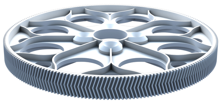
For others to look at, this is a picture of a helicopter main gear like Dave H mentioned with the herring splines.
I was wondering about the dual angled "herring bone" so I appreciate the input on the subject. I know that there would be extra manufacturing expense, but considering many will pay $80+ for a titanium screw kit in the way of saving a couple grams, I figured it only makes since for someone to offer something like this that I feel would be more significant in performance gain with smoother mechanical operation (less wear/longer bearing life), and a more linear power band and drag break effect. Maybe a company should at least consider the herring bone gearing for rear and front diff and pinions where there is a thrust factor to deal with.
For others to look at, this is a picture of a helicopter main gear like Dave H mentioned with the herring splines.
06-23-2015, 05:03 PM
#8
I seem to recall seeing some 1/8th scale kits that have helical cut ring and pinion gears for the front and rear diffs. I would assume the reasons no one has done helical cut spur and motor pinion is that straight cut ones are already an accepted standard, as well as the issues with axial load and lubrication already mentioned. I will say that it would be nice to have a quiet 1/8th electric that didn't use a plastic spur...I use metal spurs after stripping too many plastic ones, but they are pretty loud...
06-23-2015, 07:30 PM
#9
I seem to recall seeing some 1/8th scale kits that have helical cut ring and pinion gears for the front and rear diffs. I would assume the reasons no one has done helical cut spur and motor pinion is that straight cut ones are already an accepted standard, as well as the issues with axial load and lubrication already mentioned. I will say that it would be nice to have a quiet 1/8th electric that didn't use a plastic spur...I use metal spurs after stripping too many plastic ones, but they are pretty loud...
You could use a bevel cut gear on the center diff and pinion. It wouldn't put much more sideways force on the diff bearings than what the front or rear diffs see. Maybe a slightly larger bearing on the center diff would be wise though.
 06-23-2015, 07:43 PM
#10
I seem to recall seeing some 1/8th scale kits that have helical cut ring and pinion gears for the front and rear diffs. I would assume the reasons no one has done helical cut spur and motor pinion is that straight cut ones are already an accepted standard, as well as the issues with axial load and lubrication already mentioned. I will say that it would be nice to have a quiet 1/8th electric that didn't use a plastic spur...I use metal spurs after stripping too many plastic ones, but they are pretty loud...
06-23-2015, 08:06 PM
#11
06-23-2015, 08:29 PM
#12
Currently Active Users Viewing This Thread: 1 (0 members and 1 guests)
