


 1Likes
1/8 offroad electric - Belt drive conversion ?
 10-20-2012, 12:56 PM
#61

How about making the drive from motor to center diff a bevel gear? So the motor would be oriented front to back and allow more options for the other components. It would obviously require using a spur gear and pinion that's different from anything out now but might be available off the shelf from other sources.
Also I assume you are planning to enclose the belts? One small rock in the pulley and it's a dnf.
Also I assume you are planning to enclose the belts? One small rock in the pulley and it's a dnf.
 10-20-2012, 01:35 PM
#62
Ahhh, OK. I thought your second idea was what you were going to push forward with. At first inspection it looked like you didn't have enough control over the cantilever that would be imposed by the belts pulling the two pulleys away from each other, even with that external bearing.
Your latest design with the double bearing near the grey pulley will resolve any cantilever deflection contact as long as you have sufficient clearance between that pulley and the layshaft running inside it. Roller bearings are beautiful things for carrying rotational loads, but they don't handle cantilever loads very well. This is where my initial concern came from. They can allow for a lot of angular deflection if not properly placed. The short pulley tube with bearings at both ends and the shorter layshaft will counter that.
Your latest design with the double bearing near the grey pulley will resolve any cantilever deflection contact as long as you have sufficient clearance between that pulley and the layshaft running inside it. Roller bearings are beautiful things for carrying rotational loads, but they don't handle cantilever loads very well. This is where my initial concern came from. They can allow for a lot of angular deflection if not properly placed. The short pulley tube with bearings at both ends and the shorter layshaft will counter that.
In fact I agree with you. Roller bearings don't handle cantilever loads very well... and I agree with angular deflection. What I'm thinking is that the forces involved here, with the belt pulling, are not so important, and can't destroy the internal bearing. Maybe there's a way to use an other type of bearing. The best way to know if it's reliable or not, will be to make it.
I will draw other parts I need, like servo saver, ackerman.... to check if everything can be really placed on a chassis. Then I will order all the cnc parts, and will try it. Then I will be able to see if there's a bearing problem or an other problem I haven't though about. I can say you that everything you tell me is very pertinent, and I have some doubt too. I was thinking that the 2 bearings on the grey pulley, but the 2 ones at the external of the body diff, is a best solution too. The question is : is there enough space between them ?
You think this solution is the best I made : ???

Remember you can check how I done it with this pdf :
http://sylveris.free.fr/Center-diff-prototype-3D-2.pdf
And the other one here :
http://sylveris.free.fr/Center-diff-prototype-3D-3.pdf
You can see the system like this :
http://www.rctech.net/forum/nitro-of...-system-2.html
Bye !
Last edited by KOULLIT; 10-20-2012 at 02:06 PM.
10-21-2012, 11:22 AM
#63
I like this idea the best. It looks to be the most compact with the best bearing placements.
I cannot agree with you more about making it to see how everything is going to work. You can spend a lot of time designing everything in the computer, but if you have done all of your homework, designed to reasonable tolerances, and have done your best to confront all possible problems before hand, having it testing in the real world is most important.

I cannot agree with you more about making it to see how everything is going to work. You can spend a lot of time designing everything in the computer, but if you have done all of your homework, designed to reasonable tolerances, and have done your best to confront all possible problems before hand, having it testing in the real world is most important.
10-25-2012, 09:27 PM
#64
Hi,
RobCee, I finally heard you, about this bearing position.
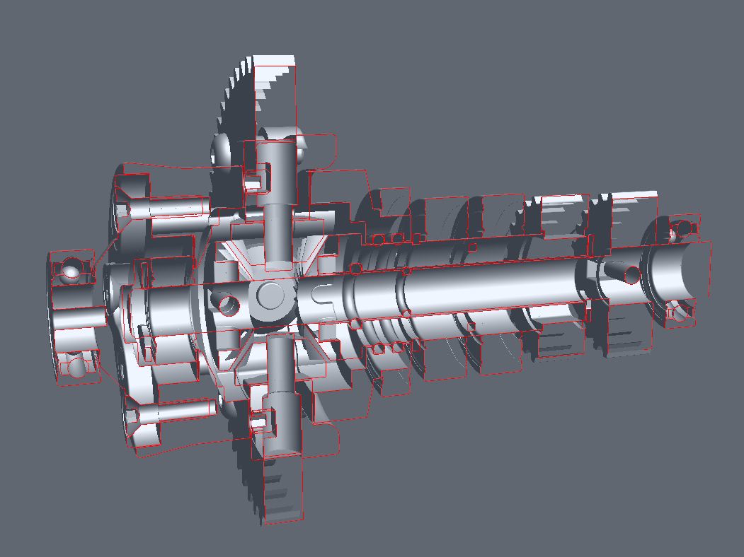
I was thinking that this bearing had not enough space to be placed here. Then I decided to draw this new differential to check if it's right with the front and rear diffs too. It seems to be possible. I have to draw the front arms because, with this bearing, the center diff has an other length and his position must be different. Then, I have to split the motor pinion, but like you can see, it's possible. I think I will keep this solution, the story continue...
This is the new mods with 44T for front and rear diffs pulleys.
The center diff pulleys are 14T.
The spur gear is 76T mod 0.8, and 21T motor pinion, for the beginning, and with the shorter ratio.
The new center diff version :


New version with 2x2S Lipo sticks :

I would like a car wich allows me to put the Lipo sticks like this too :


It's less centered than with the previous center diff system, but It's not so bad....
http://www.rctech.net/forum/nitro-of...-system-2.html
Thanks,
Bye !
RobCee, I finally heard you, about this bearing position.
I was thinking that this bearing had not enough space to be placed here. Then I decided to draw this new differential to check if it's right with the front and rear diffs too. It seems to be possible. I have to draw the front arms because, with this bearing, the center diff has an other length and his position must be different. Then, I have to split the motor pinion, but like you can see, it's possible. I think I will keep this solution, the story continue...
This is the new mods with 44T for front and rear diffs pulleys.
The center diff pulleys are 14T.
The spur gear is 76T mod 0.8, and 21T motor pinion, for the beginning, and with the shorter ratio.
The new center diff version :
New version with 2x2S Lipo sticks :
I would like a car wich allows me to put the Lipo sticks like this too :
It's less centered than with the previous center diff system, but It's not so bad....
http://www.rctech.net/forum/nitro-of...-system-2.html
Thanks,
Bye !
Last edited by KOULLIT; 12-17-2012 at 10:24 AM.
10-26-2012, 08:08 AM
#65
nice. One the agruments against the dual pack setups was the amount of imbalance you get between the heavy motor and the electronics trying to make up the difference. With this kind of layout, seems you eliminate that concern and potentionally the electronics could balance out the center diff in some manner?
Me personally would be curious to see that kind of layout but with the battery pack to the front of the car, similar to how the single pack setups are going which appears to give higher corner speed.
Anyway, very nice!
Me personally would be curious to see that kind of layout but with the battery pack to the front of the car, similar to how the single pack setups are going which appears to give higher corner speed.
Anyway, very nice!
 10-26-2012, 12:34 PM
#68
nice. One the agruments against the dual pack setups was the amount of imbalance you get between the heavy motor and the electronics trying to make up the difference. With this kind of layout, seems you eliminate that concern and potentionally the electronics could balance out the center diff in some manner?
Me personally would be curious to see that kind of layout but with the battery pack to the front of the car, similar to how the single pack setups are going which appears to give higher corner speed.
Anyway, very nice!
Me personally would be curious to see that kind of layout but with the battery pack to the front of the car, similar to how the single pack setups are going which appears to give higher corner speed.
Anyway, very nice!
I thank you for your interest and your comments. It helps me to find the real good solution, and the defaults.
I'm searching for the right balanced position of every elements : lipos, motor... but I can't find it easily. I have to save the weight of every parts in my 3D soft, then maybe I can cut the chassis in the center, and see the weight of each side, but It's not a great way to do. But I'm searching for the most available balance...
From the begining of this thread, I show you only one solution with lipos...
There are 8 different solutions with 2x2S stick lipos.
There are 4 different solutions with 4S "brick" lipos.
Then you can place the lipos like you said, to have more lipos weight on the front of the car.
I will try to draw a center differential support wich allows me to change with those 12 different ways, but just by changing the 2 belts. I think it's possible, and it's the final result I would like.
I will show you nearly all the lipos solutions.
In each solution, you can split the motor and the center diff.
I show you only the same solution, with lipos in the rear, because I want to begin by the more difficult way to do. It's more comlicated to place this sytem on the front of the car, because of the servo saver... then I want to try it before. If I can put it on the front, it will be very easy to put it on the rear. I know now I can put it on the rear, it's so easy. But I prefer work with the system on the front because I know it's difficult. Remember if I can do it, there will be many ways to change weight balance.
I will nearly show you the 12 solutions. But you have to understand 2 things :
- I have all the time I need to do it, I don't want to do it fast, because I would like to do it perfectly.
- In the begining, I will have to do it not really fine, because I will try with my RC8 parts, then this will looks like a poor job (belt protections...). But if I find the money to do it, I will show you all my prototype parts. I have many things to show that nobody has ever seen, but I'm just a single designer. I just want to try the transmission system with this type of differential.
Then I will take the time I need, to be sure I will do the best belt drive solution I can.
Rcguy76559, I don't know if I understand well, but Lipos can be placed like on the last picture I posted. If I'm right you suggest to have the lipos side by side (contact, with not play on the center of the chassis ? ). As Kufman said, I have to place the chassis brace, then it's not a solution for me. But...after one question on this forum about 4S brick lipos, I tried to put 4S brick on my chassis, and it seems it possible too. There is just a problem with chassis brace. In fact, I can draw an other rear chassis brace, but 4S is not the solution I prefer.
Excuse me for my poor english, I hope you will all understand me.
I have to draw servo saver, servo, front arms...and the most important, the center diff support... then, in a first time, I will show you how it's possible to do with lipos like you see from the begining.
Just after this, I will show you all the lipo solutions...
Thanks,
Bye !
10-26-2012, 04:05 PM
#69
Tech Regular
you can always try shorty shorty lipos
10-26-2012, 05:37 PM
#70
Hi moth898,
Are you talking about that : ??
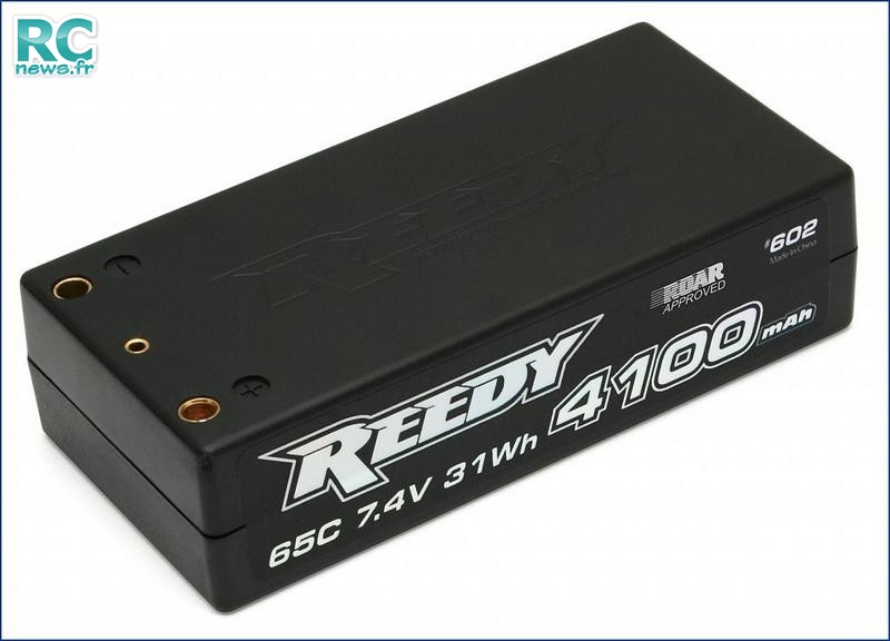
Because if it is what you are talking about, I have think to this, but just for the qualif runs. Because of the actual mah capacity of this type called "shorty", nearly 4800 for the best ones. It's a solution exactly like stick lipos, but with the facility to change weight distribution.
And there is an other solution, with the "motor/center diff" group on center of the chassis plate with one shorty Lipo pack on each side. But this solution is for the future, when we willl have more of 5500 or 6000 Mah to be sure we can do our 10mn or 12mn final runs, like it is in France. And because shorty packs are nearly 4500mah actually, I think they will be at 6000 mah near 2013-2014 !? I don't know if manufacturer will really work on them, because I don't see nobody use them. Maybe because I only read the 1/8 off-road threads on forums !? I will show you the shorty pack example too with my transmission.
It's why I believe on this center diff system, because it allows us to have many lipo solutions.
Bye !
Are you talking about that : ??
Because if it is what you are talking about, I have think to this, but just for the qualif runs. Because of the actual mah capacity of this type called "shorty", nearly 4800 for the best ones. It's a solution exactly like stick lipos, but with the facility to change weight distribution.
And there is an other solution, with the "motor/center diff" group on center of the chassis plate with one shorty Lipo pack on each side. But this solution is for the future, when we willl have more of 5500 or 6000 Mah to be sure we can do our 10mn or 12mn final runs, like it is in France. And because shorty packs are nearly 4500mah actually, I think they will be at 6000 mah near 2013-2014 !? I don't know if manufacturer will really work on them, because I don't see nobody use them. Maybe because I only read the 1/8 off-road threads on forums !? I will show you the shorty pack example too with my transmission.
It's why I believe on this center diff system, because it allows us to have many lipo solutions.
Bye !
11-08-2012, 10:44 PM
#72
Can you tell me the number of the rule you are talking about, because I can't find this lipo mention in ROAR rules.
I drew many Team Associated RC8 parts, it will be ended soon.
But I can already see the components places.
I have to do the "integration" now :
Esc will be placed on top of the left lipo, and receiver on top of the right lipo. The steering servo does'nt have so many space with this lipo and motor setting, but it's right.
I had a look at my center differential, and I know now it can be finer, and smaller, then lighter. I will work on it again, because of the pulley places, and because of the bearing sizes. I will reduce the big bearing size, and will go with 13 tooth pulley instead of 14, if possible...

Bye !
11-09-2012, 04:56 AM
#73
Look at the "Electric Chassis Rule Amendment" Rule 8.2.3
http://www.roarracing.com/?cat=26
A note on your design. If you need to gain some extra chassis room, use a different steering system. The AE steering rack takes up a lot of chassis space. Losi, HB and Tekno's setups us a lot less space.
http://www.roarracing.com/?cat=26
A note on your design. If you need to gain some extra chassis room, use a different steering system. The AE steering rack takes up a lot of chassis space. Losi, HB and Tekno's setups us a lot less space.
11-09-2012, 05:38 AM
#74
Look at the "Electric Chassis Rule Amendment" Rule 8.2.3
http://www.roarracing.com/?cat=26
A note on your design. If you need to gain some extra chassis room, use a different steering system. The AE steering rack takes up a lot of chassis space. Losi, HB and Tekno's setups us a lot less space.
http://www.roarracing.com/?cat=26
A note on your design. If you need to gain some extra chassis room, use a different steering system. The AE steering rack takes up a lot of chassis space. Losi, HB and Tekno's setups us a lot less space.
Thank you for the rule.
The different steering system from an other manufacturer, is exactly what I said this morning on the french forum. I don't know if I have to work only on the RC8 conversion, or if I have to draw my own chassis, with my arms, my steering rack...
Bye !