


Project: Team Kassanova K2v2 (2wd buggy)
 11-27-2010, 12:19 PM
#31
I know what your saying. I have considered useing B4 a-arms and suspension. But I'm just really set on the pivot ball hubs. So I'm looking at two possibilities for the a-arms. The first is 3d printing a-arms. My school has a 3d printer that prints ABSplus plastic i believe. Its not as strong as delrin or lexan but they would be lighter, look better, and be precise. The other option I'm looking at is useing certain parts of the B4 a-arms.. specifically wear the inner hinge pin goes thru and then cutting the inside of the a-arm out but keeping the outter most walls. Them custom cut lexan or delrin insert inside the a-arm and screw it to the B4 a-arms. This way I don't have to drill the hinge pin hole.. and the part that would most likely break would be the b4 part the a-arm making it possible to just replace that part. Instead of the whole a-arm. I think I might try both ideas and see which turns out better.
 11-27-2010, 11:36 PM
#32

http://www3.towerhobbies.com/cgi-bin...?&I=LXMJD9&P=7
is more along the lines of the arm i was really thinking, then you could make a "modified" center block to get the width correct. then also drill out one of the "pockets" for shock mounts.
is more along the lines of the arm i was really thinking, then you could make a "modified" center block to get the width correct. then also drill out one of the "pockets" for shock mounts.
11-28-2010, 01:44 PM
#33
The thing is with those a-arms is that they are more then 2 inches in width.. which is twice as wide as what would fit on the B4 front bulkhead and the E4 rear bulk head.
Think I'm going to look into either 3d printing the a-arms or modifying stock B4 a-arms.
Think I'm going to look into either 3d printing the a-arms or modifying stock B4 a-arms.
11-28-2010, 09:34 PM
#34
Here's an idea for you. How about 1/16 E-Revo arms? Those are pivot ball style.
12-03-2010, 02:17 PM
#36
I have been reviewing the idea of using mini-revo a-arms. The only problem with them is they are way too wide where the hinge pin goes thru them and I would have to do quiet a bit of modifying to the bulkheads.
I have to decided to try 3d printing the a-arms and see how that goes. The a-arms are down the road alittle bit..
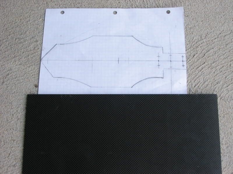
Today I received my piece of 3mm Carbon fiber for the main chassis and other parts. I got it from Rcfoam for $55 shipped. Since it is so expensive I'm going to have to be very careful not to mess up when I'm cutting the chassis. I will be cutting it with a hand-held jigsaw. The piece is very stiff and light..so definatly a good quality of carbon fiber. Next I'm going to prep the piece for cutting by covering it with painters tape. I have to make a few double checks on the chassis drawing then it will be ready to be taped to the piece of carbon with packaging tape and then the cutting will begin.
I have to decided to try 3d printing the a-arms and see how that goes. The a-arms are down the road alittle bit..
Today I received my piece of 3mm Carbon fiber for the main chassis and other parts. I got it from Rcfoam for $55 shipped. Since it is so expensive I'm going to have to be very careful not to mess up when I'm cutting the chassis. I will be cutting it with a hand-held jigsaw. The piece is very stiff and light..so definatly a good quality of carbon fiber. Next I'm going to prep the piece for cutting by covering it with painters tape. I have to make a few double checks on the chassis drawing then it will be ready to be taped to the piece of carbon with packaging tape and then the cutting will begin.
Last edited by eds24; 12-07-2010 at 05:00 PM.
12-03-2010, 08:13 PM
#37
looks like losi liked your original idea 
12-04-2010, 08:47 PM
#38
Thats what I said! The thing is Losi has stated that just about all the U.S racers will be useing the rear-motor layout.. I don't believe their mid-motor layout allows for enough traction. I'm hoping my revised layout will have enough traction to be used on the indoor clay track I will be racing it on.
12-04-2010, 11:48 PM
#39
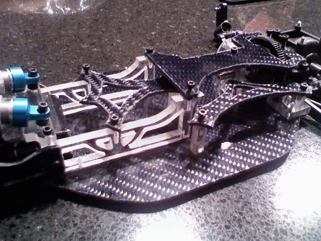
Well seeing how they sorted out mid motor gearbox, there is no way that they will have much weight in rear. They moved motor forwards quite a lot compared to others.
To ilustrate what I'm talking about - idler gear between motor and diff.
That's simply why this car won't work in mid configuration anywhere but on high grip.

To ilustrate what I'm talking about - idler gear between motor and diff.
That's simply why this car won't work in mid configuration anywhere but on high grip.
12-05-2010, 08:44 PM
#40
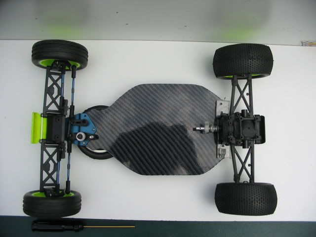
That picture slightly concerns me. Looking at the E4 rear end.. the motor is sort of far from the outdrives.. I can tilt the cvds slightly towards the front of the buggy to try and gain traction.. but I'm still abit concerned. Its ok if the buggy doesn't have traction on any other track.. but it must be able to hook up on a clay track bordering on blue groove. Subsequently, I will be driving the buggy on the same track Dustin Evans and Matt Chambers privately tested the 22. Hmm I wonder if they used mid-motor or rear-motor.
12-05-2010, 11:32 PM
#41
I have been reviewing the idea of using mini-revo a-arms. The only problem with them is they are way too wide where the hinge pin goes thru them and I would have to do quiet a bit of modifying to the bulkheads.
I have to decided to try 3d printing the a-arms and see how that goes. The a-arms are down the road alittle bit..
I have to decided to try 3d printing the a-arms and see how that goes. The a-arms are down the road alittle bit..
replacing a "factory" arm is alot easier then making 3-4 spares yourself
12-06-2010, 02:07 PM
#42
I don't have the tools to make an aluminum bulkhead.. if I where to go that route... using min-revo a-arms I would be useing otherways of modifying the bulkheads.
I understand what your saying.. 3d printing allows me to make many extra parts without much work at all.. I just have to draw the parts up in Solidworks and send them to the printer. 3d printing will allow me to make very accurate factory looking parts.
I'm still thinking about going to the LHS and picking up a set of mini-revo a-arms or atleast look at them to see if it would be possible to use them. Using them.. would bring about all kinds of other problems that need solutions.
Change of plans..
I will be cutting the chassis out of 3mm aluminum first becuase of my uncertainty with the amount of traction this mid-motor layout will provide. I don't want to cut a chassis out of carbon then find out I have to redesign it and make another chassis. I will be continuing with the planned layout for now.. I will test it and if it doesn't have enough traction I will try moving half of the saddle pack behind the diff in a custom protective case. During the testing I will be comparing the car to my B4 buggy. If the layout of the B4 seems to be performing better I will go back to a traditional layout with a rear-motor but will still have a laydown suspension, strong a-arms, and hubs, 12mm hexs, etc. Once I'm sure that a certain layout will work then I will end up cutting the chassis out of the carbon fiber
Last edited by eds24; 12-09-2010 at 10:14 PM.
12-06-2010, 03:35 PM
#43
Tech Adept
Good luck cutting carbon fiber with a hand held jig saw.
")
 12-06-2010, 07:09 PM
#45
I've cut carbon fiber with a hand-held jig saw before.. for my last version of this build.. For the smaller pieces I use a scroll saw though.
Granted the carbon I will be useing this time is different then that carbon I don't think their will be any problems.
Racex: thanks for the support.
Granted the carbon I will be useing this time is different then that carbon I don't think their will be any problems.
Racex: thanks for the support.